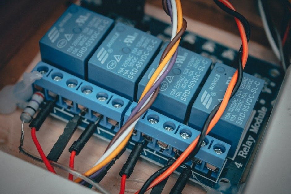
A 3-way dimmer switch allows control of lighting from multiple locations, enhancing flexibility and convenience. Understanding its wiring is crucial for proper installation and functionality, ensuring safe and efficient operation of your lighting system.
1.1 Importance of Understanding 3-Way Dimmer Switch Wiring
Understanding 3-way dimmer switch wiring is essential for safe and effective installation. Proper wiring ensures smooth control of lighting from multiple locations, preventing electrical hazards. It also enables seamless integration with smart home systems and maintains optimal dimming functionality. Incorrect wiring can lead to faulty connections, dimming issues, or even safety risks. Mastering this wiring is crucial for DIY projects and professional setups alike, ensuring reliability and efficiency in lighting control systems. Accurate knowledge helps troubleshoot common issues and avoids dangerous configurations.
1.2 Brief Overview of Dimmer Switch Functionality
A dimmer switch regulates light intensity by controlling electrical current. It uses components like thyristors or triacs to adjust voltage, enabling smooth brightness adjustment. In a 3-way setup, two switches manage power delivery, while the dimmer fine-tunes light levels. This functionality enhances ambiance and energy efficiency. Modern dimmers often include smart features for remote control, adding convenience. Proper installation ensures reliable operation, while incorrect wiring can disrupt functionality.

Components of a 3-Way Dimmer Switch
A 3-way dimmer switch includes terminals for line, load, and traveler wires, along with a grounding wire. The dimmer module regulates voltage to adjust brightness.
2.1 Understanding the Dimmer Switch Terminal Connections
A 3-way dimmer switch typically features four terminals: line (hot), load, traveler, and ground; The line terminal connects to the power source, while the load terminal links to the light fixture. The traveler terminals facilitate communication between switches in a 3-way circuit. Proper wiring ensures smooth dimming functionality. The ground terminal provides safety by directing excess current away from users. Referencing a wiring diagram is essential to avoid errors during installation. Incorrect connections can lead to malfunction or safety hazards, emphasizing the need for precise terminal identification and configuration.
2.2 Identifying Wire Types and Colors in 3-Way Circuits
In a 3-way circuit, wire colors play a critical role. The black wire is typically the hot (line) wire, while the red wire serves as the traveler, connecting both switches. The white wire, often taped with black, acts as the load wire to the fixture. The copper or green wire is the ground, ensuring safety. Correctly identifying these wires is vital for proper circuit functionality. Misidentification can lead to incorrect connections, potentially causing electrical issues or hazards. Always refer to a wiring diagram for accurate wire assignments in your specific setup.
Wiring Diagram for 3-Way Dimmer Switch
A 3-way dimmer switch wiring diagram illustrates how to connect dimmers and switches to control lighting from multiple locations. It shows the flow of power and control signals through the circuit, ensuring proper connections for safe and efficient operation.
3.1 Standard 3-Way Dimmer Switch Configuration
The standard 3-way dimmer switch configuration involves two switches controlling one light fixture. The dimmer switch is connected in series with the light, allowing for brightness adjustment. A common wire connects both switches, while traveler wires carry the control signal between them. Properly connecting the hot, neutral, and ground wires ensures safe and efficient operation. This setup is ideal for hallways, staircases, or large rooms where multiple control points are needed for convenience. Always refer to a wiring diagram to avoid errors and ensure compliance with electrical codes.
3.2 Variations in Wiring Diagrams for Different Applications
Wiring diagrams for 3-way dimmer switches can vary depending on the application. For multi-control systems, additional wires and connections are required to ensure synchronized dimming. Smart home integration may involve extra wiring for communication between switches and hubs. Some diagrams include provisions for multiple light fixtures or specialized load types. Always consult the specific wiring diagram for your setup to ensure compatibility and safety. These variations highlight the importance of careful planning and adherence to manufacturer guidelines for successful installation.

Step-by-Step Installation Guide
Start by turning off power to the circuit. Use a wiring diagram to identify connections. Prepare tools, connect wires to the dimmer switch, and mount securely. Test functionality.
4.1 Preparing the Circuit and Tools
Begin by turning off the power to the circuit at the main electrical panel. Verify the absence of voltage using a voltage tester for safety. Gather essential tools: needle-nose pliers, wire strippers, and screwdrivers. Ensure you have the correct materials, such as wire connectors and electrical tape. Review the wiring diagram to understand the connections. Identify the wires—common, travelers, and ground—and plan the connection sequence. Prepare the dimmer switch by removing any packaging and ensuring terminals are accessible. Double-check all components before starting the installation process to avoid errors.
4.2 Connecting Wires to the Dimmer Switch
Identify the common, traveler, and ground wires according to the wiring diagram. Attach the common wire to the “COM” terminal on the dimmer switch. Connect the traveler wires to the “1” and “2” terminals. Secure the ground wire to the grounding terminal or clip on the dimmer. Use needle-nose pliers to tighten connections firmly. Ensure no bare wire is exposed and connections are secure. Double-check the wiring diagram to confirm proper terminal assignments. Once all wires are connected, carefully tuck them into the wallbox to prepare for mounting the dimmer switch.
4.3 Mounting and Aligning the Dimmer Switch
After connecting the wires, carefully remove the dimmer switch from its packaging. Align the dimmer switch with the wall plate, ensuring it is straight and level. Screw the dimmer into place using the provided mounting screws. Tighten firmly but avoid over-tightening to prevent damage. Once mounted, test the dimmer by toggling it to ensure smooth operation. If the dimmer feels loose, adjust the screws. Finally, install the wall plate to complete the installation. Proper alignment ensures a professional finish and optimal functionality of the dimmer switch.

Troubleshooting Common Issues
Troubleshooting 3-way dimmer switches involves identifying common issues like flickering lights or non-working switches. These problems often stem from loose connections or incorrect wire color assignments. Checking each terminal and ensuring proper grounding can resolve many issues.
5.1 Identifying Faulty Connections
Faulty connections in a 3-way dimmer switch setup can lead to malfunctioning lights or flickering. Start by inspecting all wire connections for looseness or damage. Verify that the hot wire is correctly connected to the brass terminals and that the traveler wires are securely linked between switches. Check for any signs of wear or corrosion on the wires or terminals, as these can disrupt the circuit. Ensure all connections are tight and meet local electrical codes to prevent safety hazards and ensure reliable operation.
5.2 Resolving Dimming Functionality Problems
If the dimming function isn’t working, check for compatibility issues between the dimmer switch and the light fixture. Ensure the bulbs are dimmable and match the switch’s rating. Verify the wiring configuration against the 3-way dimmer switch wiring diagram to confirm correct connections. An overloaded circuit or incorrect traveler wire setup can also cause dimming malfunctions. Test the dimmer by swapping it with a known working switch. If issues persist, consult a licensed electrician to diagnose and repair complex wiring faults. Proper calibration of smart dimmers may also be required for optimal performance.

Safety Considerations
Always turn off power at the circuit breaker before starting work. Use insulated tools to prevent shocks. Follow the wiring diagram carefully to avoid short circuits and ensure proper grounding for safe operation.
6.1 Essential Safety Precautions for Electrical Work
Always disconnect power at the circuit breaker before starting work. Verify the circuit is de-energized using a voltage tester. Wear insulated gloves and safety goggles to protect against electrical shocks. Ensure all wires are properly grounded to prevent hazards. Never work on live circuits, and keep metal objects away from electrical components. Follow the wiring diagram meticulously to avoid misconnections. Use tools rated for electrical work to reduce risk. Maintain a clean, well-lit workspace to minimize accidents. If unsure, consult a licensed electrician to ensure compliance with safety standards.
6.2 Understanding Grounding in 3-Way Dimmer Switches
Proper grounding is crucial for safety in 3-way dimmer switch installations. The ground wire, typically bare copper, ensures safe path for excess current, preventing shocks and equipment damage. Connect the dimmer’s ground terminal to the circuit’s grounding system. Verify all connections with a voltage tester. Ensure the grounding system is intact throughout the circuit. Improper grounding can lead to dangerous conditions, so always follow local electrical codes. Grounding ensures the system operates safely, protecting both users and devices from potential hazards.

Choosing the Right Dimmer Switch
Selecting the right dimmer switch ensures compatibility with your lighting fixtures and electrical setup. Consider bulb types, wattage, and dimming functionality for optimal performance.
Verify the switch’s rating matches your circuit’s requirements to avoid overheating or malfunction. Compatibility with smart home systems is another key factor for modern installations.
7.1 Compatibility with Light Fixtures
Ensuring your dimmer switch is compatible with your light fixtures is essential for proper operation. Verify the switch supports the type of bulbs you’re using, such as LED, incandescent, or halogen.
Check the wattage rating of the dimmer to handle the total load of your fixtures. Some dimmers are designed for specific bulb types, so mismatching can lead to poor performance or damage.
Additionally, consider smart dimmers that integrate with home automation systems for advanced control. Always refer to the manufacturer’s specifications to ensure seamless compatibility and functionality.
7.2 Selecting the Correct Dimmer Switch Rating
Selecting the correct dimmer switch rating is crucial for safe and efficient operation. The switch must handle the total wattage of the connected light fixtures, ensuring it doesn’t overload. Always check the maximum wattage rating specified by the manufacturer and match it to your lighting setup. For example, a 600W dimmer switch is ideal for high-wattage fixtures, while a 150W rating may suffice for smaller setups. Proper rating selection prevents overheating, ensures smooth dimming, and avoids potential fire hazards. Never exceed the recommended wattage to maintain safety and performance.

Advanced Wiring Techniques
Explore multi-control dimming systems and smart home integration for enhanced lighting control. These advanced methods offer seamless functionality and energy efficiency, perfect for modern smart homes.
8.1 Multi-Control Dimming Systems
Multi-control dimming systems enable lighting control from multiple locations, enhancing flexibility. These systems use advanced wiring techniques to connect multiple dimmers, ensuring synchronized operation. They are ideal for large spaces or smart homes, offering precise control over lighting levels. By integrating multiple switches, users can adjust brightness seamlessly from different points, improving convenience and energy efficiency. This setup is particularly useful in areas like living rooms or staircases, where multiple access points are beneficial. Proper wiring and compatibility are crucial for reliable performance.
8.2 Integrating Smart Home Technology
Integrating smart home technology with 3-way dimmer switches enhances lighting control through voice commands or smartphone apps. Smart dimmers connect to hubs or Wi-Fi, enabling remote operation and scheduling. They often require specific wiring configurations to ensure compatibility with existing systems. Proper setup involves connecting wires to the dimmer and configuring the smart system. This integration allows for seamless automation, energy efficiency, and personalized lighting experiences. Compatibility checks and precise wiring are essential for optimal performance and reliability in smart home environments.
Proper wiring and setup of 3-way dimmer switches are crucial for functionality and safety. They enhance lighting control and energy efficiency, making them a valuable home addition. Following the guidelines ensures a successful and safe installation.
9.1 Summary of Key Points
Understanding 3-way dimmer switch wiring is essential for controlling lighting from multiple locations. Proper installation ensures safety and functionality; Key points include identifying wire types, connecting terminals correctly, and following safety guidelines. Troubleshooting common issues like faulty connections or dimming problems can prevent system malfunctions. Always use compatible dimmer switches with your light fixtures and ensure correct ratings for safe operation. Following diagrams and manufacturer instructions is crucial for successful installation and maintaining energy efficiency in your home lighting system.
9.2 Final Tips for Successful Installation
For a seamless 3-way dimmer switch installation, always follow the wiring diagram and manufacturer instructions. Ensure compatibility with your light fixtures and use the correct dimmer rating. Double-check wire connections for tightness and accuracy. Turn off the power at the circuit breaker before starting work. Use needle-nose pliers for precise wire handling in tight spaces. Test the dimmer after installation to confirm proper functionality. Consider consulting a licensed electrician if unsure about any step to avoid safety hazards and ensure a professional finish.

Leave a Reply
You must be logged in to post a comment.