Category: Manuals Page 8 of 11

1995 ford f150 manual transmission

The 1995 Ford F-150 manual transmission offers durability and control‚ enhancing the truck’s performance for both on-road and off-road driving. Its robust design provides smooth shifting and fuel efficiency‚ making it a preferred choice for drivers seeking precision and reliability. This transmission played a key role in the F-150’s reputation as a versatile and dependable work vehicle.

1.1 Overview of the 1995 Ford F-150

The 1995 Ford F-150 is a robust pickup truck known for its durability and versatility. It features a range of engine options‚ including a 4.9L inline-6 and a 5.8L V8‚ paired with manual or automatic transmissions. Designed for both work and recreation‚ the F-150 offers a comfortable cabin‚ ample cargo space‚ and strong towing capabilities. Its reliability and performance made it a popular choice for work-oriented users and outdoor enthusiasts alike.

1.2 Importance of the Manual Transmission in the 1995 F-150

The manual transmission in the 1995 F-150 was crucial for drivers seeking control and fuel efficiency. It allowed precise gear shifts‚ enhancing towing and hauling capabilities. For off-road use‚ manual transmissions provided better torque management‚ making them ideal for challenging terrains. Additionally‚ it appealed to cost-conscious buyers as it was often more affordable and required less maintenance compared to automatic transmissions‚ ensuring long-term durability and performance.

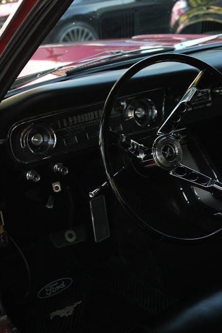
Specifications of the 1995 Ford F-150 Manual Transmission

The 1995 Ford F-150 manual transmission featured a durable‚ lightweight design with precise shifting. It offered a range of gear ratios‚ optimizing both fuel efficiency and towing capacity‚ ensuring reliable performance for various driving conditions.

2.1 Types of Manual Transmissions Available

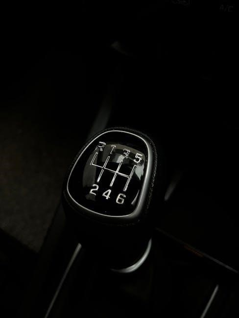
The 1995 Ford F-150 offered two primary manual transmission options: the M5OD-R1 and M5OD-R2. The M5OD-R1 was a 5-speed unit designed for lighter-duty applications‚ providing smooth shifting and fuel efficiency. The M5OD-R2‚ also a 5-speed‚ was built for heavier-duty use‚ featuring a higher torque capacity and stronger internal components‚ making it ideal for towing and hauling. Both transmissions were known for their durability and reliability‚ catering to different driver needs.

2.2 Key Features and Capabilities

The 1995 Ford F-150 manual transmission featured synchronized gears for smooth shifting and a durable construction to handle heavy-duty tasks. It offered exceptional control for both city driving and off-road adventures‚ with gear ratios optimized for towing and hauling. The transmission’s compatibility with various engine options‚ including the 4.9L inline-six and 5.0L V8‚ ensured versatility and performance‚ making it a reliable choice for work and play.

Maintenance and Care for the Manual Transmission

Regular maintenance of the 1995 Ford F-150 manual transmission includes checking transmission fluid levels‚ replacing the filter‚ and ensuring proper gear lubrication. Avoid extreme temperatures and use approved fluids for optimal performance.

3.1 Recommended Maintenance Schedule

For the 1995 Ford F-150 manual transmission‚ regular maintenance is essential. Check the transmission fluid level every 3‚000 to 5‚000 miles and top it off as needed. Replace the transmission filter annually or every 15‚000 miles. Inspect and lubricate gears every 30‚000 miles. Use only approved transmission fluid (Ford M2C-166-H) to ensure optimal performance. Avoid extreme temperatures and consult the owner’s manual for additional recommendations to maintain longevity and functionality.

3.2 Common Issues and DIY Fixes

Common issues with the 1995 Ford F-150 manual transmission include low fluid levels‚ worn synchronizers‚ and bearing noise. To address these‚ check the fluid level regularly and top it off with Ford M2C-166-H fluid. For worn synchronizers‚ replace them with genuine parts. If bearings are noisy‚ inspect and replace them as needed. DIY fixes often require basic tools and a repair manual for guidance‚ ensuring the transmission runs smoothly and efficiently over time.

Performance and Capabilities

The 1995 Ford F-150 manual transmission enhances towing and hauling capabilities‚ delivering smooth shifts and fuel efficiency. Its robust design excels in both on-road and off-road scenarios‚ ensuring reliable performance for heavy-duty tasks and adventurous drives alike.

4.1 Towing and Hauling Capacity

The 1995 Ford F-150 manual transmission is engineered to maximize towing and hauling efficiency. Paired with a 5.0L V8 or 4.9L inline-six engine‚ it delivers precise control for heavy loads. The transmission’s gearing ensures optimal torque distribution‚ allowing the truck to handle up to 5‚000 pounds of towing capacity and 1‚500 pounds of payload. This capability makes it ideal for both work and recreational use‚ offering reliability and strength in demanding conditions.

4.2 Off-Road Performance

The 1995 Ford F-150 manual transmission excels in off-road conditions‚ offering precise control over gear shifts and torque delivery. Its robust design ensures smooth operation on uneven terrains‚ while the optional four-wheel-drive system enhances traction and stability. The manual transmission’s gearing optimizes low-end power‚ making it ideal for navigating steep inclines and rough trails with confidence and reliability‚ ensuring a superior off-road experience.

Troubleshooting Common Problems

Common issues with the 1995 Ford F-150 manual transmission include gear grinding‚ slipping‚ and fluid leaks. Regular checks and timely repairs can prevent major failures.

5.1 Identifying Transmission Noises and Leaks

Common noises like grinding or whining can indicate worn bearings or gear issues. Leaks around the transmission pan gasket or seals signal fluid loss. Check for drops beneath the truck and inspect the pan for cracks. Low or dirty transmission fluid can exacerbate problems. Regular inspection and fluid checks‚ as outlined in the owner’s manual‚ help catch issues early‚ preventing costly repairs.

5;2 Repair Options and Costs

Repair options for the 1995 Ford F-150 manual transmission vary depending on the issue. DIY fixes for minor leaks or worn seals can cost $50-$200. Professional repairs for damaged bearings or gears may range from $500 to $1‚500. Replacing the entire transmission can cost between $1‚500 and $3‚000‚ depending on whether it’s rebuilt or new. Regular maintenance‚ like fluid changes‚ can prevent costly repairs and extend transmission life.

History and Evolution of the Ford F-150 Manual Transmission

The 1995 Ford F-150 manual transmission represents a key milestone in the F-Series lineage‚ offering enhanced durability and performance while maintaining its reputation as a reliable work truck.

6.1 Historical Context of the 1995 Model

The 1995 Ford F-150 manual transmission emerged during a period of significant advancements in automotive technology. It was part of the ninth generation of the F-Series‚ known for its improved durability and performance. The manual transmission was a crucial feature‚ catering to both work-oriented users and off-road enthusiasts. This model marked a shift towards more robust and reliable drivetrains‚ setting the stage for future innovations in the F-150 lineup.

6.2 Comparison with Modern Manual Transmissions

Modern manual transmissions in the Ford F-150 have evolved significantly since 1995‚ featuring advanced technologies like improved synchronizers‚ bearings‚ and gear ratios. Today’s models offer smoother shifting‚ better fuel efficiency‚ and reduced driver fatigue. The 1995 version‚ while durable‚ lacks the refined engineering and electronic integration of contemporary systems. However‚ its simplicity and ruggedness continue to appeal to enthusiasts of classic trucks.

Owner Manual Insights

The 1995 Ford F-150 owner’s manual provides essential information for optimal transmission performance‚ including maintenance tips and troubleshooting guides to ensure longevity and reliability.

7.1 Essential Information from the 1995 Ford F-150 Owner’s Manual

The 1995 Ford F-150 owner’s manual emphasizes regular maintenance for the manual transmission‚ including fluid checks and proper driving techniques to avoid wear. It outlines a schedule for transmission service and provides troubleshooting tips for common issues like slipping gears or low fluid levels. The manual also stresses the importance of using the correct transmission fluid and avoiding extreme temperatures.

7.2 Tips for Optimal Transmission Performance

To maintain the 1995 Ford F-150 manual transmission’s performance‚ avoid aggressive driving and monitor fluid levels regularly. Use the recommended transmission fluid type and ensure proper shifting techniques. Avoid riding the clutch‚ as it can cause excessive wear. Gradual acceleration and avoiding unnecessary gear changes will extend the transmission’s lifespan. Regular inspections and addressing minor issues promptly can prevent major repairs. Always refer to the owner’s manual for specific guidelines.

DIY Modifications and Upgrades

Popular DIY upgrades for the 1995 Ford F-150 manual transmission include installing a lightweight flywheel and performance clutch kit for improved acceleration and smoother shifting.

8.1 Popular Aftermarket Modifications

Popular aftermarket modifications for the 1995 Ford F-150 manual transmission include installing a lightweight flywheel and performance clutch kit for improved acceleration and smoother shifting. Upgrading to a high-performance gear set can enhance durability and torque capacity. Additionally‚ aftermarket transmission coolers and heavy-duty drivetrain components are popular for towing and off-road applications‚ ensuring optimal performance under heavy loads or extreme conditions.

8.2 Safety Considerations for Transmission Upgrades

When upgrading the 1995 Ford F-150 manual transmission‚ prioritize safety by ensuring proper installation of aftermarket parts. Always follow torque specifications and use high-quality‚ compatible components to avoid premature wear or failure. Improper modifications can lead to loss of control or system malfunction. Consulting a professional mechanic is highly recommended to guarantee safety and optimal performance during and after upgrades.

The 1995 Ford F-150 manual transmission stands as a testament to durability and reliability‚ offering precise control and timeless appeal for both work and enthusiasts alike.

9.1 Final Thoughts on the 1995 Ford F-150 Manual Transmission

The 1995 Ford F-150 manual transmission remains a standout for its durability and performance‚ offering drivers precise control and a connection to the truck’s rugged heritage. Its ease of use and reliability make it a favorite among both enthusiasts and practical users‚ ensuring its legacy as a timeless component of Ford’s iconic pickup.

9.2 Recommendations for Potential Buyers

Potential buyers of the 1995 Ford F-150 with a manual transmission should prioritize checking the transmission’s condition‚ ensuring smooth shifting and no leaks. Review maintenance records and consider a pre-purchase inspection to avoid costly repairs. Test driving is essential to assess performance. This model remains a reliable choice for those seeking a durable‚ hands-on driving experience with classic appeal.

stanley fatmax 1000a manual

The Stanley Fatmax 1000A is a professional-grade power station designed for jump-starting vehicles, charging electronics, and inflating tires. It combines portability with versatility for emergency and everyday use.

1.1 Overview of the Stanley Fatmax 1000A Power Station

The Stanley Fatmax 1000A Power Station is a versatile, professional-grade device designed for jump-starting vehicles, charging electronics, and inflating tires. It features a peak capacity of 1000A and a 500A instant start, making it suitable for cars, trucks, and motorcycles. With a built-in 120 PSI compressor and multiple power outlets, it offers a reliable solution for emergencies and everyday use. The unit is portable and built to withstand heavy-duty applications, ensuring power availability wherever needed. Its user-friendly design and comprehensive manual make it accessible for both professionals and DIY enthusiasts.

1.2 Importance of the User Manual

The user manual is essential for understanding the Stanley Fatmax 1000A’s features, safe operation, and maintenance. It provides detailed instructions for jump-starting, charging, and using the built-in compressor. The manual also outlines safety precautions and troubleshooting tips, ensuring optimal performance and preventing potential hazards. Reading and following the manual is crucial for maximizing the device’s functionality and lifespan while maintaining user safety.

Key Features and Specifications

The Stanley Fatmax 1000A features a 1000A peak amp rating, lead-acid battery, portable power outlets, USB charging ports, and a built-in compressor with a backlight gauge.

2;1 Peak Amp Rating and Battery Type

The Stanley Fatmax 1000A boasts a 1000A peak amp rating, delivering robust power for jump-starting vehicles. It features a maintenance-free lead-acid battery, ensuring reliability and durability. Designed for heavy-duty use, the battery provides consistent performance across various applications, from emergency starts to powering devices. Always adhere to the manual’s safety guidelines for optimal battery life and performance.

2.2 Portable Power Outlets and USB Charging

The Stanley Fatmax 1000A includes multiple portable power outlets, such as 120V AC outlets and USB ports, for versatile charging. These outlets support a 500-watt capacity, ideal for charging personal electronics, power tools, and small appliances. The USB ports provide fast and convenient charging for smartphones and other devices, making it a reliable power source for both emergency and everyday use.

2.3 Built-in Compressor and Backlight Gauge

The Stanley Fatmax 1000A features a built-in 120 PSI compressor with a backlight gauge, enabling easy tire inflation and pressure monitoring. The compressor is ideal for inflating tires, inflatable boats, and other equipment. The backlight gauge ensures clear visibility in low-light conditions, making it convenient for nighttime or emergency use. This feature enhances portability and versatility, providing a reliable solution for various inflation needs.

Safety Precautions

Always wear protective eyewear and ensure proper ventilation when using the Stanley Fatmax 1000A. Keep batteries away from children and avoid short circuits. Follow the manual’s guidelines to prevent accidents and ensure safe operation.

3.1 General Safety Guidelines

Always read the user manual before use to understand safety procedures. Wear protective eyewear and ensure good ventilation. Avoid short circuits and improper connections. Keep the unit away from children. Never modify the device or use damaged cables. Store batteries in a cool, dry place. Follow all warnings and instructions to prevent accidents and ensure safe operation of the Stanley Fatmax 1000A.

3.2 Handling Lead-Acid Batteries Safely

When handling the Stanley Fatmax 1000A’s lead-acid battery, always wear protective eyewear and gloves. Avoid direct contact with battery acid, as it can cause severe burns or blindness. Ensure immediate assistance is available in case of emergencies. Prevent short circuits and improper connections, as they can lead to explosions. Never modify the battery or use damaged cables, and always follow the manual’s guidelines for safe handling and maintenance.

Installation and Setup

Begin by unpacking and inspecting the unit for damage. Connect the Stanley Fatmax 1000A to a power source for charging, following the manual’s setup guidelines carefully.

4.1 Unpacking and Initial Inspection

Begin by carefully unpacking the Stanley Fatmax 1000A from its box. Inspect the unit for any visible damage or defects. Ensure all components, including the power station, clamps, and cables, are included. Verify the battery terminals are clean and secure. Refer to the manual for a detailed list of contents and initial inspection checklist to ensure everything is in proper condition before use.

4.2 Connecting the Unit to a Power Source

To charge the Stanley Fatmax 1000A, use the provided wall charger or a compatible alternative. Plug the charger into a standard AC outlet and connect it to the unit’s charging port. Ensure the unit is turned off during charging. Refer to the manual for recommended charging times and procedures. Always check the charger and cables for damage before use to ensure safe and efficient charging.

Using the Stanley Fatmax 1000A

The Stanley Fatmax 1000A is a versatile power station designed for jump-starting vehicles, charging electronics, and inflating tires. It combines portability with reliability for emergency and everyday use.

5.1 Jump-Starting a Vehicle

Connect the positive clamp to the vehicle’s battery terminal and the negative clamp to a metal surface. Ensure all connections are secure and not touching any moving parts. Start the vehicle and let it run for a few minutes to recharge the battery. Always follow the sequence outlined in the manual to avoid damage or safety risks.

5.2 Charging Personal Electronics

The Stanley Fatmax 1000A features multiple USB ports and AC outlets for convenient charging of smartphones, tablets, and laptops. Use the appropriate cables and adapters for your devices. Ensure the unit is fully charged or connected to a power source before use. Always monitor the battery level to avoid overloading the system. This makes it ideal for camping or emergency situations.

Charging the Power Station

The Stanley Fatmax 1000A can be charged via an AC outlet or through solar panels. The unit features LED indicators to show charging progress and completion status.

6.1 Recommended Charging Methods

The Stanley Fatmax 1000A can be charged using an AC wall outlet or solar panels. For AC charging, use the provided charger and plug it into a standard 120V outlet. Solar charging is ideal for outdoor use, requiring a compatible solar panel. Ensure the unit is turned off during charging to prevent overheating. Always consult the user manual for detailed charging instructions and safety precautions to maintain battery health and performance.

6.2 Charging Time and Indicators

The Stanley Fatmax 1000A typically charges to full capacity within 8-10 hours using the AC adapter. LED indicators display the charging status: green for fully charged, red for charging in progress, and flashing red for potential issues. Monitor these indicators to ensure proper charging and avoid overcharging, which can degrade battery life. Refer to the manual for specific time guidelines and indicator meanings.

Maintenance and Storage

Regularly inspect terminals for corrosion and clean them to maintain optimal performance. Store the unit in a cool, dry place away from direct sunlight to prolong battery life.

7.1 Regular Maintenance Tips

Ensure optimal performance by regularly inspecting terminals for corrosion and cleaning them with a wire brush. Recharge the battery every 30 days if unused for an extended period. Avoid extreme temperatures and moisture. Check the compressor and hose for damage. Store the unit upright in a cool, dry place, away from direct sunlight, to preserve battery health and overall functionality.

  • Inspect terminals for corrosion regularly.
  • Clean terminals with a wire brush if necessary.
  • Recharge the battery every 30 days during storage.
  • Avoid exposure to extreme temperatures and moisture.
  • Check the compressor and hose for damage.
  • Store upright in a cool, dry, dark place.

7.2 Proper Storage Conditions

Store the Stanley Fatmax 1000A in a cool, dry place away from direct sunlight and moisture. Avoid extreme temperatures and humidity. Keep the unit upright to prevent battery leakage. Ensure the battery is charged to at least 50% before long-term storage. Do not store in a vehicle or areas prone to humidity. Regularly check the battery level during storage to maintain performance and longevity.

  • Store in a cool, dry environment.
  • Avoid direct sunlight and moisture.
  • Keep the unit upright to prevent leakage.
  • Charge to 50% before long-term storage.
  • Check battery levels during storage.

Troubleshooting Common Issues

The Stanley Fatmax 1000A may face issues like battery drain or malfunction. Check connections, ensure proper charging, and reset the unit if necessary. Refer to the manual for detailed solutions.

  • Battery issues: Check charge levels and connections.
  • Malfunction: Reset the unit as instructed.
  • Consult the manual for specific troubleshooting steps.

8.1 Diagnosing Battery Problems

Diagnosing battery issues in the Stanley Fatmax 1000A involves checking charge levels, connections, and signs of damage. Ensure the battery is fully charged and terminals are clean. Look for swelling, leaks, or corrosion. If issues persist, refer to the manual for specific troubleshooting steps or consider professional assistance. Regular maintenance can prevent many battery-related problems.

  • Check charge levels and connections.
  • Inspect for physical damage or corrosion.
  • Consult the manual for detailed diagnostic procedures.

8.2 Resetting the Power Station

To reset the Stanley Fatmax 1000A, first disconnect it from any power source or connected devices. Turn off all outlets and allow the unit to cool down for 10 minutes. Plug it back in and check for normal operation. If issues persist, press and hold the reset button (if equipped) for 5 seconds. Always follow safety guidelines during the reset process.

  • Disconnect from power and devices.
  • Wait 10 minutes before reconnecting.
  • Use the reset button if necessary.

Technical Specifications

The Stanley Fatmax 1000A features a 12V DC system with 1,000A peak battery capacity and 500A instant start. It includes 120 PSI compressor and weighs 25 lbs.

  • Peak Amp Rating: 1,000A
  • Battery Type: Maintenance-free
  • AC Power Outlets: 2
  • USB Ports: 2
  • Compressor PSI: 120
  • Weight: 25 lbs

Perfect for portable power needs, balancing portability and performance.

9.1 Boost Ampere and Instant Start

The Stanley Fatmax 1000A delivers a robust 12V DC system with 1,000A peak amp rating and 500A instant start functionality. This ensures rapid energy delivery for jump-starting vehicles. The instant start feature provides quick power flow when proper connections are made, enhancing safety and efficiency during emergencies. It is designed to handle demanding tasks with reliability and precision.

9.2 Weight and Portability

The Stanley Fatmax 1000A is designed for portability, featuring a compact and durable construction. While the exact weight isn’t specified, it includes a built-in handle for easy transport. Its lightweight design ensures mobility, making it ideal for on-the-go use in emergencies or workshops. The unit is built to withstand heavy-duty applications while remaining easy to carry and store.

Accessories and Compatible Tools

Stanley Fatmax 1000A supports various accessories like USB adapters, inflators, and storage cases. It is compatible with Stanley’s V20 cordless tools and Pro-Stack storage systems for enhanced functionality.

10.1 Recommended Accessories

For optimal use, consider accessories like USB adapters, inflators, and storage cases. Safety gear such as gloves and eyewear is also recommended. These tools enhance functionality and ensure safe operation, complementing the Stanley Fatmax 1000A’s capabilities for jump-starting, charging, and inflating tires efficiently in various situations.

10.2 Compatibility with Other Stanley Products

The Stanley Fatmax 1000A is designed to integrate seamlessly with other Stanley tools and systems, such as the V20 Cordless Power Tool System and PRO-STACK Storage Solutions. This compatibility ensures enhanced functionality and versatility, allowing users to create a comprehensive workshop setup. The product also works alongside the Stanley Track Wall System, offering organized storage and easy access to all your tools and accessories.

Warranty and Support

The Stanley Fatmax 1000A is backed by a comprehensive warranty; Register your product for extended coverage and contact customer support at (877) 571-2391 for assistance.

11.1 Warranty Coverage Details

The Stanley Fatmax 1000A is covered by a 2-year limited warranty, protecting against manufacturing defects. Registration is required to activate the warranty. For inquiries or claims, contact customer support at (877) 571-2391. This warranty ensures reliable performance and peace of mind for users. Terms and conditions apply, so review the manual for full details.

11.2 Customer Support Contact Information

For assistance with the Stanley Fatmax 1000A, contact customer support at (877) 571-2391. Email inquiries can be directed to the provided address on the official Stanley website. Support is available to address troubleshooting, warranty claims, and general product questions. Visit the Stanley Fatmax support page for additional resources and contact options.

The Stanley Fatmax 1000A is a reliable power solution for jump-starting vehicles and charging devices. Follow the manual for optimal performance and safety.

12.1 Final Tips for Optimal Use

Always read the manual before first use and ensure proper connections. Regularly charge the unit and store it in a cool, dry place. Wear protective eyewear during use and avoid overloading the power station. For best performance, follow the recommended charging cycles and consult the manual for compatibility with your vehicle or devices. Safe usage ensures longevity and reliability of the Stanley Fatmax 1000A.

12.2 Importance of Following the Manual

Adhering to the Stanley Fatmax 1000A manual ensures safe and effective operation. It provides critical safety precautions, proper usage guidelines, and troubleshooting tips. Following the manual prevents battery damage, electrical hazards, and ensures compatibility with devices. Ignoring instructions can lead to equipment failure or personal injury. Always refer to the manual for optimal performance and to maintain warranty coverage.

honeywell t6 pro z-wave manual

Welcome to the Honeywell T6 Pro Z-Wave manual, your comprehensive guide to installing, configuring, and operating this advanced smart thermostat. Designed for homeowners and installers, this manual ensures seamless integration with Z-Wave systems, offering enhanced smart home capabilities and energy-efficient temperature control. By following this guide, you’ll unlock the full potential of the Honeywell T6 Pro Z-Wave, optimizing comfort and reducing energy consumption. Let’s get started!

1.1 Overview of the Honeywell T6 Pro Z-Wave Thermostat

The Honeywell T6 Pro Z-Wave Thermostat is a cutting-edge smart home device designed to enhance your comfort and energy efficiency. With its intuitive touch screen interface, this thermostat offers seamless integration with Z-Wave systems, allowing you to control your home’s temperature remotely. It features advanced geofencing capabilities and adaptive learning technology to anticipate your heating and cooling needs. The T6 Pro Z-Wave is compatible with various smart home platforms, making it a versatile addition to any smart home setup. Its energy-efficient design helps reduce your utility bills, combining convenience with cost savings and enhancing overall home comfort.

1.2 Importance of the Manual for Proper Installation and Use

This manual is essential for the correct installation and operation of the Honeywell T6 Pro Z-Wave Thermostat. It provides detailed instructions to ensure a seamless setup process, avoiding potential errors that could compromise performance. The guide includes safety precautions, compatibility checks, and troubleshooting tips to address common issues. By following the manual, users can optimize the thermostat’s features, such as geofencing and smart home integration, while minimizing energy waste. Proper use of this manual ensures the thermostat functions efficiently, delivering the desired comfort and energy savings. Refer to it regularly for maintenance and advanced feature utilization.

Key Features of the Honeywell T6 Pro Z-Wave Thermostat

The Honeywell T6 Pro Z-Wave Thermostat boasts Z-Wave compatibility, smart home integration, and advanced energy-saving features like geofencing and customizable heating/cooling schedules, ensuring efficient and convenient temperature control.

2.1 Z-Wave Compatibility and Smart Home Integration

The Honeywell T6 Pro Z-Wave Thermostat seamlessly integrates with Z-Wave smart home systems, enabling remote temperature control and voice command functionality through compatible hubs. This compatibility allows homeowners to connect their thermostat with other Z-Wave devices, creating a unified smart home ecosystem. Users can adjust settings via smartphone apps or voice assistants like Amazon Alexa, enhancing convenience and energy efficiency. The thermostat’s Z-Wave capabilities ensure reliable communication with smart hubs, making it easy to automate heating and cooling schedules based on occupancy or preferences, thereby optimizing comfort and reducing energy consumption.

2.2 Temperature Control and Energy Efficiency Features

The Honeywell T6 Pro Z-Wave Thermostat offers advanced temperature control with geofencing and smart scheduling, optimizing comfort and energy savings. It adapts to your home’s heating and cooling needs, preventing overheating or overcooling. Energy-efficient features include automatic adjustments based on occupancy and customizable settings to minimize energy waste. The thermostat also provides detailed energy usage reports, helping you track and reduce consumption. With its smart learning capabilities, it ensures your home remains comfortable while lowering utility bills, making it an ideal choice for eco-conscious homeowners seeking seamless temperature management and cost savings.

Installation and Setup Guide

Begin by verifying system compatibility and gathering tools. Follow step-by-step wiring instructions, ensuring all connections are secure. Complete the setup by configuring network settings and integrating with your Z-Wave hub for seamless smart home control.

3.1 Pre-Installation Requirements and Tools Needed

To ensure a smooth installation, verify compatibility with your HVAC system and check if a C-wire is present. Gather essential tools: screwdrivers, voltage tester, and drill.

Shut off power to the HVAC system before starting. Ensure the thermostat location is accessible and free from obstructions. Familiarize yourself with the manual to understand the wiring diagram and setup process.

3.2 Step-by-Step Installation Process

3.3 Pairing the Thermostat with a Z-Wave Hub

To pair the Honeywell T6 Pro Z-Wave thermostat with your smart home hub, start by enabling the hub’s inclusion mode. Navigate to the thermostat’s menu, select Z-Wave Setup, and choose Pair Device. The thermostat will enter pairing mode, indicated by a blinking LED. Once connected, the hub will confirm the pairing. If issues arise, reset the thermostat by pressing and holding the menu button for 10 seconds, then reinitialize the pairing process. Ensure both devices are within range for a stable connection. Refer to your hub’s manual for specific pairing instructions, as procedures may vary. Proper pairing ensures seamless smart home integration.

Advanced Features and Customization

Explore the Honeywell T6 Pro Z-Wave’s advanced features, including customizable temperature schedules, geofencing, and smart scene integration. Tailor settings to optimize energy use and comfort seamlessly.

4.1 Geofencing and Location-Based Temperature Control

The Honeywell T6 Pro Z-Wave thermostat offers geofencing, allowing you to control temperatures based on your location. Using your smartphone’s GPS, the system automatically adjusts settings when you leave or arrive home, optimizing energy use and comfort. This feature ensures your home is warm or cool by the time you arrive and conserves energy when you’re away. Customize the geofence radius and temperature preferences through the app or Z-Wave hub for a seamless, location-aware heating and cooling experience tailored to your lifestyle.

4.2 Smart Scenes and Customizable Heating/Cooling Schedules

The Honeywell T6 Pro Z-Wave thermostat supports smart scenes, enabling you to create custom heating and cooling schedules tailored to your daily routines. Using the app or Z-Wave hub, you can program temperature adjustments for specific times, such as waking up, leaving for work, or returning home. Additionally, you can integrate the thermostat into smart home scenes, synchronizing it with other devices like lights or security systems. This feature enhances convenience, energy efficiency, and comfort, allowing you to maintain an ideal environment while minimizing energy waste. Customize your schedules to fit your lifestyle and preferences seamlessly.

Troubleshooting Common Issues

This section helps identify and resolve common issues with the Honeywell T6 Pro Z-Wave thermostat, ensuring optimal performance, comfort, and energy efficiency. Solutions cover connectivity, temperature inaccuracies, and scheduling errors.

5.1 Common Problems and Their Solutions

Identifying and resolving issues with the Honeywell T6 Pro Z-Wave thermostat ensures uninterrupted performance. Common problems include connectivity issues, inconsistent temperature readings, or unresponsiveness. To address connectivity, restart the hub and thermostat. For temperature inaccuracies, check sensor calibration or wiring connections. If the thermostat fails to turn on, verify power sources and circuit breaker status. Software updates often resolve firmware-related issues. Regularly updating the system and ensuring proper installation can prevent many problems. Refer to the manual for detailed troubleshooting steps to restore functionality and maintain optimal performance.

5.2 Resetting the Thermostat and Reinitializing Settings

Resetting the Honeywell T6 Pro Z-Wave thermostat can resolve persistent issues or prepare it for a new installation. To reset, press and hold the “Menu” and “Back” buttons simultaneously for 10 seconds. This action restores factory settings, erasing all custom configurations. After resetting, reinitialize the thermostat by reconnecting it to your Z-Wave hub and reconfiguring your preferred settings. Ensure the thermostat is properly powered and synced with your smart home system. If issues persist, consult the manual or contact Honeywell support for further assistance.

The Honeywell T6 Pro Z-Wave manual provides comprehensive guidance for maximizing efficiency and comfort. Its advanced features and smart integration ensure optimal performance, making it a top choice for modern homes.

6.1 Summary of Key Points and Benefits

The Honeywell T6 Pro Z-Wave manual offers a detailed guide to maximizing the thermostat’s potential. Key benefits include seamless Z-Wave integration, advanced temperature control, and energy-saving features. Its user-friendly interface and customizable schedules enhance comfort and efficiency. The manual ensures proper installation and troubleshooting, providing long-term reliability. Honeywell’s global expertise and commitment to innovation make the T6 Pro a standout solution for smart home systems. By following the manual, users can optimize their heating and cooling systems, reducing energy consumption while maintaining optimal comfort. This thermostat is a testament to Honeywell’s leadership in home automation and sustainability.

6.2 Final Tips for Optimal Use of the Honeywell T6 Pro Z-Wave

To maximize your Honeywell T6 Pro Z-Wave experience, ensure regular software updates for the latest features and security. Customize temperature settings based on your schedule and preferences for energy efficiency. Utilize geofencing to automatically adjust temperatures when you leave or arrive home. Regularly clean the thermostat’s sensors to maintain accuracy. Schedule periodic maintenance checks to ensure optimal performance. Explore smart home integrations to enhance functionality. Monitor energy usage reports to identify savings opportunities. By following these tips, you’ll enjoy a seamless, efficient, and comfortable smart home experience with your Honeywell T6 Pro Z-Wave thermostat.

echo srm 210 manual

This manual provides essential guidance for the Echo SRM-210, a high-performance, lightweight, and gasoline-powered trimmer/brushcutter․ It covers safety, operation, and maintenance to ensure optimal use․

1․1 Overview of the Echo SRM-210 Trimmer/Brushcutter

The Echo SRM-210 is a high-performance, lightweight trimmer/brushcutter designed for efficient cutting․ It features a 21․2cc engine, offering robust power for trimming grass and tackling thick vegetation․ The unit includes a dual-line head for precision cutting and is compatible with metal blades for heavier tasks․ Its ergonomic design ensures comfort during extended use․ This versatile tool is ideal for maintaining large outdoor spaces, combining power and portability for professional-grade results․

1․2 Importance of Reading the Manual

Reading the Echo SRM-210 manual is crucial for safe and effective operation․ It provides detailed guidance on assembly, starting procedures, and maintenance, ensuring optimal performance․ The manual also outlines essential safety precautions to prevent accidents and equipment damage․ Understanding the content helps users troubleshoot common issues and adhere to environmental guidelines․ Failure to follow the manual may result in improper use, leading to potential hazards or reduced product lifespan․ Always refer to the manual before operating the trimmer/brushcutter․

Safety Precautions and Guidelines

Always wear protective gear like gloves and goggles․ Ensure the area is clear of debris․ Avoid loose clothing and follow manual warnings for safe operation․

2․1 General Safety Tips for Operating the Echo SRM-210

Wear protective gear, including gloves, safety glasses, and sturdy footwear․ Ensure the area is clear of obstacles and bystanders․ Avoid wearing loose clothing that may get caught․ Keep children and pets away while operating․ Maintain a firm grip on the handlebars and stay balanced․ Never operate the trimmer when fatigued or in poor visibility․ Regularly inspect the equipment for damage or wear․

2․2 Understanding Safety Manuals and Warnings

Read both the operator’s manual and safety manual thoroughly before use․ They contain crucial information for safe operation and maintenance․ Pay attention to warning labels on the equipment, highlighting potential hazards․ Follow all instructions carefully to prevent accidents; Familiarize yourself with emergency stop procedures and proper handling techniques․ Understanding these guidelines ensures safe and efficient use of the Echo SRM-210 trimmer/brushcutter․

Key Features and Specifications of the Echo SRM-210

The Echo SRM-210 features a 21․2cc engine, lightweight design, and high-performance capabilities․ It includes dual-line head compatibility and interchangeable shields for nylon lines or metal blades․

3․1 Engine and Performance Details

The Echo SRM-210 is powered by a 21․2cc two-stroke, air-cooled engine, delivering high torque for efficient cutting․ It features a reliable ignition system and precision carburetor for consistent performance․ The engine is designed for low emissions and fuel efficiency, making it suitable for both residential and light commercial use․ Proper maintenance, including regular air filter cleaning and oil checks, ensures optimal engine longevity and power output․ This robust engine allows the SRM-210 to handle tough trimming tasks with ease․

3․2 Design and Build Quality

The Echo SRM-210 features a lightweight yet durable design, with a robust construction that ensures longevity․ Its ergonomic handle and balanced build provide comfort during extended use․ The trimmer is equipped with a high-quality cutting head and shield system, offering versatility for both nylon lines and metal blades․ The engine is positioned for optimal balance, reducing user fatigue․ Built with high-grade materials, the SRM-210 is designed to withstand rigorous use while maintaining precise control and efficiency․

Operational Guide for the Echo SRM-210

This section provides step-by-step instructions for starting, operating, and stopping the Echo SRM-210․ It includes guidelines for efficient trimming and brush cutting, ensuring safe and effective use․

4․1 Assembly and Initial Setup Instructions

The Echo SRM-210 requires careful assembly before use․ Attach the cutting head securely, adjust the handles to a comfortable position, and ensure the harness is properly fitted․ The U-Turn head and Dual Line Head are essential components for efficient trimming․ Refer to the parts catalog for identifying components․ Always follow the safety manual instructions to ensure proper setup and safe operation․

4․2 Starting and Stopping the Engine

To start the Echo SRM-210, ensure the choke is in the correct position, prime the engine, and pull the starter rope firmly․ For stopping, turn off the throttle and allow the engine to idle before switching off the ignition․ Always follow the manual’s guidelines for smooth operation and safety․

Maintenance and Care for the Echo SRM-210

Regular maintenance ensures optimal performance․ Clean or replace air filters, sharpen blades, and check fuel lines․ Follow the manual for detailed care routines and troubleshooting tips․

5․1 Regular Maintenance Tasks

Regular maintenance is crucial for the Echo SRM-210’s longevity and efficiency․ Ensure to clean or replace the air filter frequently, sharpen the cutting blade, and inspect fuel lines for damage․ Lubricate moving parts and check the spark plug for wear․ Refer to the manual for specific intervals and procedures to keep the trimmer running smoothly and safely throughout its lifespan․

5․2 Troubleshooting Common Issues

Common issues with the Echo SRM-210 include engine failure to start, poor cutting performance, or overheating․ Check fuel quality, ensure the air filter is clean, and verify spark plug functionality․ Inspect the cutting line for wear and proper tension․ Address blockages in the fuel line or carburetor․ For persistent problems, consult the manual or contact customer support for detailed repair guidance to restore optimal performance quickly and effectively․

Parts Catalog and Accessories for the Echo SRM-210

The Echo SRM-210 parts catalog offers replacement components like the U-Turn Head and Dual Line Head; Accessories include cutting lines, blades, and ergonomic handles․ Refer to the manual for model-specific details and compatibility to ensure proper fitment and optimal performance․

6․1 Identifying and Ordering Replacement Parts

To identify replacement parts for the Echo SRM-210, refer to the official parts catalog, which lists components like the U-Turn Head and Dual Line Head․ Ensure compatibility by matching model numbers (e․g․, SRM-210) and serial numbers (e․g․, S/N: 07001001)․ For ordering, consult Echo’s customer support or visit their official website․ Genuine Echo parts are recommended to maintain performance and safety, and they can be purchased through authorized dealers or online retailers․

6․2 Compatible Accessories and Attachments

The Echo SRM-210 supports various accessories to enhance functionality․ The U-Turn Head and Dual Line Head are popular options for efficient trimming․ Additional attachments like steel shields for metal blades and nylon line accessories are available․ For compatibility, refer to Echo’s official parts catalog or website․ Genuine Echo accessories ensure optimal performance and safety․ Visit authorized dealers or Echo’s online store to explore compatible attachments tailored for your SRM-210 model․

Storage and Transportation Guidelines

Store the Echo SRM-210 in a dry, protected area․ Clean the unit before storage and use protective coverings․ Transport securely to avoid damage․

7․1 Proper Storage Techniques

Store the Echo SRM-210 in a clean, dry, and secure location․ Remove any debris, drain old fuel, and use protective coverings to prevent dust․ Keep it upright in a well-ventilated area, away from direct sunlight and moisture․ Ensure the unit is out of children’s reach and avoid extreme temperatures․ Regularly inspect for damage before storing․ Proper storage maintains performance and prevents corrosion, ensuring longevity and reliability for future use․

7․2 Safe Transportation Methods

Secure the Echo SRM-210 firmly in a vehicle to prevent movement during transit․ Protect the cutting head and engine from damage using a cover or padding․ Ensure the fuel tank is empty or tightly sealed to avoid leaks․ Keep the trimmer upright to prevent fuel from spilling; Use protective coverings to shield against dust and moisture․ Regularly inspect for any loose parts and ensure they are securely fastened before transporting․ Proper transportation safeguards the equipment and ensures safe handling during relocation․

Environmental Considerations

Use the Echo SRM-210 responsibly to minimize environmental impact․ Follow eco-friendly practices and proper disposal guidelines for waste materials and fluids․ Recycle when possible․

8․1 Eco-Friendly Usage Tips

To minimize environmental impact, use the Echo SRM-210 responsibly․ Optimize fuel consumption by maintaining proper engine performance․ Avoid excessive idling and ensure correct fuel-to-oil ratios․ Use eco-friendly accessories and avoid over-trimming to preserve vegetation․ Dispose of waste materials, like used oil and filters, responsibly․ Regular maintenance reduces emissions and ensures efficient operation․ Follow local regulations for environmentally safe practices when using the trimmer/brushcutter․

8․2 Disposal and Recycling Information

Proper disposal and recycling of the Echo SRM-210 and its components are crucial for environmental protection․ Dispose of used oil, filters, and batteries responsibly through designated facilities․ Recycle metal and plastic parts whenever possible․ Ensure all fuel is drained and stored safely before disposal․ Check local regulations for specific guidelines on hazardous waste management․ Eco-friendly disposal practices help reduce the environmental impact of the product at the end of its life cycle․

Additional Resources and Support

Access the official Echo website for the SRM-210 manual, PDF downloads, and troubleshooting guides․ Contact customer service for warranty inquiries and technical assistance through authorized dealers․

9․1 Online Manuals and PDF Downloads

Echo provides comprehensive online resources for the SRM-210․ Users can download the official PDF manual from Echo’s website, ensuring access to detailed instructions, safety guidelines, and troubleshooting tips․ Additional materials, such as parts catalogs and maintenance guides, are also available for download․ These resources are essential for optimal performance and safe operation of the trimmer/brushcutter, offering a convenient way to reference information anytime․

9․2 Customer Service and Warranty Information

Echo offers dedicated customer support for the SRM-210, accessible via phone, email, or their official website․ The product is backed by a 5-year consumer warranty and a 2-year professional warranty, covering manufacturing defects․ Proper registration and maintenance are required to ensure warranty validity․ Users are encouraged to contact Echo support for assistance or visit the website for detailed warranty terms․ Always refer to the manual for specific conditions and guidelines to maintain coverage․

The Echo SRM-210 manual provides comprehensive guidance for safe and effective use․ By following its instructions, users can master the trimmer’s operation, ensuring optimal performance and longevity․

10․1 Final Tips for Optimal Use

Regular maintenance ensures peak performance and longevity․ Always check the idle speed and follow storage guidelines․ Keep the unit clean and store it in a dry place․ Refer to the safety manual for troubleshooting common issues․ Proper handling and adherence to guidelines will enhance your experience with the Echo SRM-210․ Safe operation and routine care are key to maximizing efficiency and durability․

eurotherm 3216 user manual

The Eurotherm 3216 is a high-performance PID temperature controller designed for precise temperature management in industrial applications. It offers advanced PID control, digital communications, and robust alarm functions.

Installation

Ensure the controller is mounted in a dry, cool environment. Verify supply voltage matches requirements (85-264VAC) before installation. Secure the unit firmly to prevent movement during operation.

2.1 Initial Checks

Before installing the Eurotherm 3216, perform a series of initial checks to ensure proper functionality. Verify that the supply voltage matches the controller’s requirements, which range from 85VAC to 264VAC. Check for any visible damage to the unit or its components. Ensure all terminals and connections are clean and free from corrosion. Review the manual to confirm the controller is configured correctly for your application. Additionally, verify that the unit is compatible with your system’s communication protocols if digital communication is required. These checks help prevent installation issues and ensure reliable operation. Proper preparation is key to a smooth setup process.

2.2 Mounting the Controller

Mount the Eurotherm 3216 in a suitable enclosure or panel to ensure proper protection and accessibility. The controller’s compact design allows for easy installation in standard DIN rail setups. Ensure the mounting location is dry, well-ventilated, and free from excessive heat sources. Use the provided fixing clips or screws to secure the unit firmly to the panel. For added protection, install the controller in an enclosure with an IP65 or NEMA 4X rating to prevent dust and moisture ingress. Proper mounting ensures reliable operation and extends the lifespan of the controller. Always follow the manufacturer’s guidelines for installation to maintain warranty validity and performance integrity.

Wiring

Wiring the Eurotherm 3216 involves connecting the power supply, input sensors, and output devices. Ensure all connections are secure and correctly configured for proper operation. Refer to the manual for specific wiring diagrams and guidelines to avoid installation errors.

3.1 Power Supply Requirements

The Eurotherm 3216 requires a supply voltage ranging from 85VAC to 264VAC, ensuring compatibility with various power sources. It is a standard controller with a compact design, measuring 48mm in width and height, making it suitable for most industrial control panels. For optimal performance, the controller should be connected to a dedicated circuit with an appropriate rating to prevent voltage fluctuations. Proper grounding is essential to maintain accuracy and prevent interference. Always refer to the manual for specific wiring guidelines to ensure safe and reliable operation. Using a dedicated circuit helps avoid power-related issues and ensures compliance with safety standards.

3.2 Input/Output Configuration

The Eurotherm 3216 allows for flexible input/output configuration to meet various application needs. It supports up to three configurable outputs, which can be set for control, alarm, or re-transmission purposes. Inputs include a current transformer option for enhanced measurement accuracy. The controller’s digital communication capabilities enable seamless integration with external systems. Outputs can be configured to control heating, cooling, or alarms, ensuring precise temperature management. The configuration process is straightforward, with options available through the controller’s interface or external software. Proper setup ensures optimal performance, and the manual provides detailed guidance for customizing inputs and outputs to suit specific industrial requirements.

Configuration

The Eurotherm 3216 configuration involves setting PID parameters, alarms, and advanced functions like dwell timers and self-tuning. The Quick Start Wizard simplifies initial setup, while manual adjustments allow fine-tuning for precise control.

4.1 Using the Quick Start Wizard

The Quick Start Wizard streamlines the Eurotherm 3216 configuration process, guiding users through initial setup efficiently. It prompts for control mode, alarm settings, and output type selection. The wizard allows customization of PID parameters and advanced features like self-tuning. Users can review and modify settings before saving. This tool is ideal for both novice and experienced users, ensuring rapid deployment while maintaining flexibility. The wizard also supports advanced configurations, such as dwell timers and communication settings, enabling tailored solutions. By following the step-by-step interface, users can achieve optimal performance quickly, minimizing downtime and ensuring precise temperature control from the start.

4.2 Setting PID Parameters

Setting PID parameters on the Eurotherm 3216 involves configuring the proportional, integral, and derivative values to achieve precise temperature control. The controller allows manual adjustment of these parameters or enables automatic tuning using the self-tuning feature. Users can select from predefined PID profiles or customize settings based on specific application requirements. The integral and derivative times can be fine-tuned to optimize response and stability. Additionally, features like integral wind-up prevention and derivative filtering are available to enhance control accuracy. These adjustments ensure the controller adapts effectively to varying process dynamics, delivering reliable and consistent temperature regulation across diverse industrial applications.

Features

The Eurotherm 3216 features advanced PID control, digital communications, and configurable alarms. It offers optional current transformer inputs and supports multiple output configurations for flexible process management.

5.1 Alarm Functions

The Eurotherm 3216 includes comprehensive alarm functions to monitor temperature deviations, sensor faults, and output failures. Users can configure alarms for high or low limits, ensuring timely alerts for process deviations. These alarms enhance system safety and prevent operational disruptions. Customizable alarm settings allow tailored responses to specific conditions, improving overall process control and reliability. The controller’s alarm system is integral to maintaining consistent and precise temperature regulation in industrial environments.

5.2 Communication Options

The Eurotherm 3216 supports various communication options, enabling seamless integration with industrial networks and control systems. It features digital communication capabilities, allowing data exchange via protocols such as Modbus RTU or TCP/IP. This ensures efficient monitoring and control from central systems. Additionally, the controller can connect to external devices like PCs or PLCs, facilitating remote configuration and data logging. Optional communication modules further expand connectivity, supporting advanced industrial automation needs. These features make the Eurotherm 3216 highly adaptable for modern industrial communication requirements, enhancing system interoperability and operational efficiency.

Operation

Operating the Eurotherm 3216 involves initializing the controller, monitoring temperature, and utilizing its control functions. Once powered on, the controller displays the process temperature and setpoint. Users can navigate the menu to adjust parameters or activate advanced features. The Quick Start Wizard simplifies initial setup, while PID control ensures precise temperature regulation. Alarms trigger alerts for deviations, and the dwell timer manages heating cycles. The controller’s interface is user-friendly, allowing easy access to operational modes, data logging, and configuration adjustments. Regular operation ensures reliable temperature management, making the Eurotherm 3216 a robust choice for industrial applications.

Advanced Functions

The Eurotherm 3216 offers advanced functions such as self-tuning PID control, adaptive control, and valve position control for precise temperature regulation. It supports digital communications for seamless integration with industrial systems. The controller features configurable outputs for control, alarm, or re-transmission purposes, enhancing flexibility. Advanced timers, including dwell and delayed start, optimize process control. Data logging and remote monitoring capabilities enable efficient process tracking. The IP65 and NEMA 4X ratings ensure durability in harsh environments. These advanced functions make the Eurotherm 3216 a versatile and reliable solution for complex industrial temperature control applications, ensuring high performance and adaptability to various operational needs.

Troubleshooting

Troubleshooting the Eurotherm 3216 involves identifying common issues such as power supply problems, wiring faults, or incorrect configurations. Check the power supply voltage to ensure it meets the required range of 85VAC to 264VAC. Verify all connections for proper wiring and tightness. If alarms are triggered, refer to the alarm codes in the manual for specific solutions. Use the controller’s diagnostic tools to identify errors and review the self-tuning PID parameters for optimal performance. Ensure digital communications are correctly configured if issues arise with data transmission. For persistent problems, consult the detailed troubleshooting guide in the user manual or contact Eurotherm support for assistance.

Maintenance

Regular maintenance of the Eurotherm 3216 ensures optimal performance and longevity. Clean the controller’s exterior and internal components periodically to prevent dust buildup. Check and tighten all electrical connections to maintain proper operation. Update firmware regularly to access new features and improvements. Ensure the power supply meets the required specifications to avoid damage. Inspect and replace worn or damaged parts promptly. Perform routine checks on input/output configurations and alarm settings to ensure accuracy. Refer to the user manual for detailed maintenance schedules and procedures. Proper upkeep helps prevent unexpected downtime and ensures reliable temperature control in industrial applications.

The Eurotherm 3216 is a versatile and reliable temperature controller designed for precise industrial applications. By following the installation, wiring, and configuration guidelines outlined in this manual, users can optimize its performance. Regular maintenance and updates ensure longevity and efficiency. The controller’s advanced features, such as PID control and alarm functions, make it a valuable asset for temperature management. For further assistance, refer to the Eurotherm website or contact support. Proper use and care of the Eurotherm 3216 will enhance operational reliability and contribute to achieving consistent temperature control in various industrial processes. This concludes the Eurotherm 3216 user manual guide.

manual scrobbler

Manual scrobblers allow users to track their music listening habits by inputting data manually, offering control and accuracy for dedicated music enthusiasts. Early systems required entering CD barcodes, evolving into tools like Legacy Scrobbler, which simplifies manual tracking while maintaining data integrity for precise music analytics.

1.1 Definition and Purpose

A manual scrobbler is a tool enabling users to log their music listening habits by inputting data manually, ensuring accurate tracking of songs, artists, and albums. Initially requiring CD barcode entry, manual scrobblers evolved to simplify tracking while maintaining data integrity, allowing users to manage and analyze their music preferences effectively, providing insights into listening patterns and preferences with precision and control;

1.2 Importance in Music Tracking

Manual scrobblers play a crucial role in music tracking by enabling precise data entry, ensuring accurate insights into listening habits and preferences. They allow users to maintain detailed records of their music consumption, which is invaluable for personal analytics and discovering trends over time. Tools like Legacy Scrobbler simplify this process, making manual tracking efficient and reliable for dedicated music enthusiasts seeking comprehensive listening data and statistics.

Historical Evolution of Manual Scrobbling

Manual scrobbling began with users entering data like CD barcodes, evolving as tools like Legacy Scrobbler simplified the process, blending traditional control with modern efficiency for precise tracking.

2.1 Early Days of Last.fm

Last.fm’s early days required users to manually input data, such as CD barcodes, to track their music listening habits. This method, though cumbersome, laid the foundation for music tracking. Users tolerated the inconvenience, but it highlighted the need for automation, eventually leading to the development of automatic scrobbling features that streamlined the process while maintaining data accuracy and user engagement.

2.2 Transition to Automatic Scrobbling

Last.fm shifted from manual data entry to automatic scrobbling, enhancing user convenience. Automatic features, such as correcting artist and track name misspellings, improved accuracy. However, this transition posed challenges, including slower data processing due to updates in older datasets and charts, balancing efficiency with data integrity for a seamless user experience.

Step-by-Step Guide to Manual Scrobbling

Manually track your music by entering artist and track details, using tools like Legacy Scrobbler to simplify the process and ensure accurate data entry for precise records.

3.1 Setting Up Your Account

Start by creating an account on platforms like Last.fm or using apps such as Legacy Scrobbler. Download and install the application, then configure settings like API keys. Ensure your music player is connected to the scrobbling service. Set preferences for automatic or manual data submission. Verify your account by following in-app instructions to begin tracking your music listening habits seamlessly.

3.2 Inputting Data Manually

Manually inputting data involves entering the artist, track name, and album details into your scrobbling application. Ensure accuracy by cross-checking spellings and selecting the correct album from dropdown suggestions. For timestamp accuracy, specify when the track was played; Some apps allow batch entries for multiple tracks, saving time. Always review your entries for consistency and correctness before submitting.

3.4 Troubleshooting Common Issues

Common issues with manual scrobbling include misspelled track names and duplicate entries. Cross-reference data with reliable sources to ensure accuracy. If scrobbles fail to upload, check your internet connection and app settings. For timestamp inaccuracies, use system timestamps or log plays immediately. Regularly audit your scrobble list to identify and correct errors, ensuring your music tracking remains consistent and reliable over time.

Pros and Cons of Manual Scrobbling

Manual scrobbling offers precision and control for music tracking but can be time-consuming and prone to human error, requiring careful data entry and verification.

4.1 Advantages of Manual Entry

Manual scrobbling provides precise control over music tracking, allowing users to correct misspelled tracks and ensure accurate data entry. It enables dedicated enthusiasts to maintain detailed listening histories, especially for older albums or tracks not automatically detected. This method also offers reliability for devices lacking automatic scrobbling support, ensuring no listens are missed, and it caters to users who value meticulous data management and personalized analytics.

4.2 Disadvantages and Limitations

Manual scrobbling is time-consuming and prone to errors, requiring users to input data meticulously. It can be frustrating when dealing with misspelled tracks or older systems, which slow down data processing. The need for manual corrections and updates adds inconvenience, making it less efficient for users seeking seamless tracking experiences compared to automatic methods.

Tools and Applications for Manual Scrobbling

Legacy Scrobbler and other applications enable manual tracking, offering compatibility across platforms like macOS and Windows. These tools simplify data entry and improve accuracy for precise music tracking.

5.1 Legacy Scrobbler Overview

Legacy Scrobbler is a popular application designed for manual music tracking, available on macOS and Windows. It simplifies the process of inputting song data, allowing users to maintain precise records of their listening habits. The tool is praised for its user-friendly interface and compatibility with platforms like Last.fm, ensuring accurate and efficient scrobbling for music enthusiasts who value detailed analytics and control over their data.

5.2 Features and Compatibility

Legacy Scrobbler supports platforms like Last.fm, enabling seamless integration for music tracking. It offers batch import and manual entry options, providing flexibility and control. The application is compatible with various operating systems and music platforms, ensuring wide accessibility. Its features cater to both casual listeners and dedicated enthusiasts, making it a versatile tool for accurate and efficient music data management.

5.3 Other Notable Applications

Beyond Legacy Scrobbler, tools like Shazam and Tunebat offer unique features for manual scrobbling. Shazam provides real-time song identification, while Tunebat allows manual editing of scrobble data. Additionally, applications like MusicBrainz Picard enable users to tag and import music data, enhancing manual tracking capabilities. These tools cater to different user preferences, ensuring a tailored experience for music enthusiasts seeking precise control over their listening data.

Troubleshooting Common Issues

Common issues include data entry errors and misspelled tracks. Users can resolve these by cross-checking metadata or using tools like Legacy Scrobbler to ensure accuracy.

6.1 Resolving Data Entry Errors

Common data entry errors include typos or incorrect track formats. To resolve these, users can cross-reference metadata or use tools like Legacy Scrobbler to ensure accuracy. Additionally, double-checking artist names and track titles before submission helps minimize mistakes. Regularly updating scrobbling tools and adhering to standard formatting guidelines can also prevent errors, ensuring reliable music tracking and maintaining data consistency for accurate analytics.

6.2 Managing Misspelled Tracks

Misspelled tracks can lead to inaccurate music tracking. To address this, users can manually correct track names or use auto-correction features available in some tools. Ensuring consistent formatting and cross-referencing with reliable metadata sources helps prevent errors. Additionally, regular audits of scrobbled data and updating entries promptly can maintain data accuracy and improve overall music tracking efficiency for better insights into listening habits.

Data Management Best Practices

Regularly organizing and backing up scrobble data ensures accuracy and prevents loss. Using consistent formatting and updating entries promptly maintains data integrity for reliable music tracking insights.

7.1 Organizing Your Scrobbles

Maintaining orderly scrobble data involves creating playlists, using consistent tags, and updating entries promptly. Regularly reviewing for accuracy ensures reliable insights. Correcting misspelled tracks and organizing by artist or genre enhances data clarity. Tools like Legacy Scrobbler can help automate parts of this process, ensuring your music tracking remains precise and well-structured over time.

7.2 Correcting and Updating Data

Correcting and updating scrobble data ensures accuracy and consistency. Regularly review entries for misspellings or errors, leveraging tools like Legacy Scrobbler to streamline corrections. Updating data promptly reflects true listening habits, enhancing insights and personal analytics. This careful process maintains the integrity of your music tracking, providing reliable and meaningful data for long-term analysis and comparison.

Community Feedback and User Experiences

Users share mixed feedback on manual scrobblers, praising accuracy but noting inconvenience. Forums highlight discussions on tracking habits and comparisons, while reviews emphasize the tool’s niche appeal for dedicated users.

8.1 User Testimonials and Reviews

Users appreciate manual scrobblers for their accuracy and control, despite the inconvenience. Many praise tools like Legacy Scrobbler for simplifying tracking. Some highlight how manual entry fosters deeper engagement with music. Others appreciate corrections for misspelled tracks, enhancing data quality. Overall, testimonials reflect a dedicated niche of users valuing precise analytics and the satisfaction of maintaining their listening history with meticulous care and attention to detail.

8.2 Community Discussions and Forums

Online forums buzz with discussions about manual scrobblers, as users share experiences and tips. Many highlight Legacy Scrobbler’s effectiveness and ease of use. Others discuss challenges, like correcting misspelled tracks, and collaborate on solutions. These communities foster a sense of camaraderie, with users exchanging tools and strategies to enhance their music tracking. Such forums remain vital for troubleshooting and discovering new apps tailored to their needs.

Manual scrobblers have evolved from barcode entry to tools like Legacy Scrobbler, offering precise music tracking. Their accuracy and community support ensure lasting relevance for dedicated users.

9.1 Summary of Key Points

Manual scrobblers have transitioned from barcode entry to advanced tools like Legacy Scrobbler, ensuring accurate music tracking. Early systems required manual input, while modern tools streamline the process, correcting misspellings and enhancing data integrity. These tools remain essential for dedicated users seeking precise music analytics and personalized listening insights, fostering a community driven by shared musical experiences and detailed tracking capabilities.

9.2 Future of Manual Scrobbling

Manual scrobbling’s future lies in integrating advanced features while maintaining its core simplicity. Tools like Legacy Scrobbler may evolve with AI-driven suggestions and cross-platform compatibility, enhancing user convenience. Despite automatic tracking’s rise, manual scrobbling’s precision and control ensure its relevance, catering to dedicated enthusiasts who value accuracy and customization in their music tracking experiences.

yamaha rx-v367 receiver manual

Welcome to the Yamaha RX-V367 Receiver Manual! This guide helps you understand and optimize your AV receiver’s features‚ ensuring an enhanced home theater experience․ Explore setup‚ configuration‚ and troubleshooting tips for seamless operation․

1․1 Overview of the Yamaha RX-V367 Receiver

The Yamaha RX-V367 is a versatile AV receiver designed for home theater systems‚ offering 5․1-channel surround sound and 1080p HDMI support․ It features automatic speaker calibration and compatibility with various audio formats․ This entry-level receiver supports 3D video pass-through and provides multiple connectivity options‚ making it ideal for enhancing your entertainment experience․ The manual guides you through its features and setup for optimal performance․

1․2 Importance of the Manual for Setup and Operation

The manual is essential for proper setup and operation of the Yamaha RX-V367 receiver․ It provides detailed instructions for installation‚ configuration‚ and troubleshooting․ Understanding the manual ensures optimal performance‚ customizes settings to your preference‚ and prevents potential damage․ By following the guide‚ you can unlock all features‚ ensuring a seamless and enhanced home theater experience tailored to your specific audio and video needs․

System Requirements and Compatibility

The Yamaha RX-V367 receiver is compatible with HDMI 1․4a‚ supporting 3D video pass-through and various audio formats․ It works with 5․1-channel speaker systems‚ ensuring optimal performance and compatibility for a wide range of home theater setups and configurations․

2․1 Compatible Speaker Systems and Audio Formats

The Yamaha RX-V367 supports 5․1-channel surround sound systems‚ ensuring immersive audio․ It is compatible with various speaker setups‚ including front‚ center‚ and rear channels‚ and subwoofers․ The receiver also supports popular audio formats like Dolby Digital and DTS‚ delivering high-quality sound․ Proper speaker configuration and calibration are essential for optimal performance‚ as detailed in later sections of this manual․

2․2 HDMI Version and 3D Video Pass-Through Capability

The Yamaha RX-V367 features HDMI version 1․4‚ supporting 3D video pass-through for enhanced visual experiences․ This capability ensures seamless transmission of 1080p signals from connected devices like Blu-ray players and gaming consoles․ The receiver’s firmware update enables 3D video pass-through‚ making it compatible with modern entertainment systems․ This feature is ideal for users seeking immersive home theater experiences without signal degradation․

Installation and Initial Setup

Unbox the Yamaha RX-V367‚ position it in a well-ventilated area‚ and connect cables․ Follow the manual for physical installation and configure basic settings to ensure proper functionality and readiness for use․

3․1 Unboxing and Physical Installation Steps

Begin by carefully unboxing the Yamaha RX-V367 receiver and its accessories․ Place the unit in a well-ventilated area to prevent overheating․ Connect the power cord and ensure the receiver is positioned away from moisture․ Next‚ connect HDMI and analog cables to the appropriate ports‚ following the manual’s guidance for proper installation․ Avoid touching internal components to prevent damage․

3․2 Initial Configuration and Connectivity Options

After unboxing‚ proceed to connect your devices using HDMI or analog inputs․ Configure the receiver by selecting the appropriate HDMI port for your TV and enabling features like HDMI pass-through․ Use the remote to navigate the on-screen menu for input assignment and speaker setup․ Ensure all cables are securely connected to their respective ports for optimal performance and clear audio output․

Remote Control Programming

Learn how to program your TV remote control codes into the Yamaha remote for seamless control․ Customize functions to enhance convenience and streamline your home theater experience․

4․1 Programming TV Remote Control Codes into the Yamaha Remote

To program your TV remote control codes into the Yamaha RX-V367 remote‚ follow these steps:

  1. Locate the TV remote control codes compatible with your Yamaha RX-V367 receiver․ These codes are typically found in the Yamaha manual or on the official Yamaha support website․
  2. Enter the remote into programming mode by pressing and holding the appropriate buttons (e․g․‚ Power and Volume Down) until the remote’s indicator light flashes․
  3. Use the numeric keypad to input the TV remote control code․ Press the “Enter” or “OK” button to confirm the code․
  4. Test the remote by attempting to control your TV․ If it doesn’t work‚ repeat the process with a different code until you find one that functions properly․

Ensure you have the correct codes and follow the sequence carefully to successfully program the remote․

4․2 Customizing Remote Control Functions for Convenience

Customize your Yamaha RX-V367 remote for ease of use․ Assign frequently used functions to specific buttons‚ creating a personalized control layout․ For example‚ you can set the remote to instantly switch between audio modes or inputs․ Additionally‚ some remotes allow for macro commands‚ enabling multiple actions with a single button press․ This feature enhances convenience‚ ensuring seamless control over your home theater system․

Speaker Configuration and Calibration

Properly configure your speakers and calibrate the system for optimal sound․ Use automatic or manual adjustments to match your setup and listening environment‚ ensuring balanced audio performance;

5․1 Automatic Speaker Acoustic Parameter Adjustment

The Yamaha RX-V367 features automatic acoustic parameter adjustment‚ optimizing sound for your speakers and room․ This advanced feature analyzes speaker characteristics and listening environment‚ ensuring balanced audio reproduction․ Simply run the setup process‚ and the receiver will automatically calibrate settings for optimal performance‚ delivering clear and immersive sound effortlessly‚ tailored to your specific setup․ This feature enhances overall audio quality and convenience‚ making it ideal for home theaters․ By automating adjustments‚ it simplifies the process‚ ensuring precise sound calibration without manual fine-tuning‚ which can be complex for users․ The result is a seamless and enjoyable listening experience‚ with minimal effort required from the user․ This functionality demonstrates Yamaha’s commitment to user-friendly technology and high-quality audio solutions․

5․2 Manual Adjustment for Optimal Sound Quality

For precise control‚ manual adjustment allows fine-tuning of speaker settings to achieve optimal sound quality․ Adjust parameters like crossover frequencies‚ channel levels‚ and delay settings to suit your listening environment․ This feature is ideal for audiophiles seeking customized audio performance․ Use the on-screen menu to access these settings and tailor the sound to your preference‚ ensuring a personalized and immersive listening experience․ Manual adjustments provide flexibility and accuracy‚ enhancing overall audio fidelity․ By tweaking settings manually‚ users can optimize the receiver’s output for their specific speaker setup and room acoustics‚ resulting in a more refined and engaging sound․ This level of customization ensures that the Yamaha RX-V367 delivers exceptional performance‚ catering to discerning listeners who value precise audio control․ The manual adjustment process is straightforward‚ allowing users to experiment and find the perfect balance for their home theater system․ With careful calibration‚ the receiver can produce sound that is both dynamic and nuanced‚ fulfilling the demands of high-quality audio reproduction․ Additionally‚ manual adjustments enable users to compensate for unique room characteristics‚ such as echo or uneven frequency response‚ ensuring a more accurate soundstage․ By taking advantage of these manual controls‚ users can unlock the full potential of their Yamaha RX-V367 receiver‚ enjoying a tailored audio experience that meets their exact preferences․ This level of customization is a testament to Yamaha’s dedication to providing versatile and high-performance audio solutions for home entertainment systems․

Firmware Update Instructions

Keep your Yamaha RX-V367 up-to-date by following the firmware update guide․ Download the latest version from Yamaha’s website‚ unzip‚ and burn the WAV file to a disc․ Follow the installation manual carefully to ensure a smooth update process and access new features like 3D video pass-through capability․ Regular updates enhance performance and add functionality to your receiver․

6․1 Step-by-Step Guide for Updating Firmware

Updating the Yamaha RX-V367 firmware is straightforward․ First‚ download the firmware from the official Yamaha website․ Extract the ZIP file and burn the WAV file to a CD․ Insert the disc into the receiver‚ navigate to the update menu via the remote‚ and follow on-screen instructions․ The process is automatic‚ ensuring compatibility and enhanced features like 3D video pass-through․ Always refer to the installation manual for detailed steps to avoid errors and ensure a successful update․

6․2 Benefits of the Latest Firmware Version

The latest firmware version enhances the Yamaha RX-V367 receiver’s performance‚ adding features like 3D video pass-through and improving HDMI compatibility․ It ensures smoother operation‚ better sound quality‚ and compatibility with the latest devices․ Regular updates also fix bugs‚ improve stability‚ and expand functionality‚ ensuring your receiver stays up-to-date with emerging technologies for an optimal home theater experience․

Advanced Audio Settings

Explore advanced audio settings to customize your listening experience․ Adjust parameters for optimal sound in different environments and immerse yourself in 5․1 channel surround sound capabilities․

7․1 Adjusting Audio Parameters for Different Listening Environments

Customize your audio experience by adjusting parameters to suit various environments․ The Yamaha RX-V367 allows acoustic adjustments to match your speakers and space‚ ensuring optimal sound quality․ Utilize automatic settings for precise calibration or manually tweak levels for personal preference․ This feature enhances clarity and immersion‚ making every listening session a delight․

7․2 Utilizing 5․1 Channel Surround Sound Features

Maximize your home theater experience with the Yamaha RX-V367’s 5․1 channel surround sound․ This feature delivers immersive audio‚ with dedicated channels for front‚ center‚ rear‚ and subwoofer speakers․ Enhanced by automatic speaker calibration‚ it ensures balanced sound distribution․ Perfect for movies and gaming‚ this setup creates a cinematic environment‚ drawing you deeper into the action with precise‚ vibrant audio reproduction․

Connecting External Devices

Connect your HDMI and analog devices seamlessly to the Yamaha RX-V367․ Ensure proper cable connections for optimal performance and enjoy high-quality audio and video synchronization effortlessly․

8․1 Guidelines for Connecting HDMI and Analog Inputs

Connect external devices to the Yamaha RX-V367 by using HDMI or analog inputs․ For HDMI‚ ensure the cables are securely plugged into the correct ports to support up to 1080p resolution and 3D pass-through․ Analog devices can be connected via RCA or optical inputs․ Match the source device’s output to the receiver’s input for proper signal routing․ This setup ensures high-quality audio and video synchronization‚ avoiding performance issues․

8․2 Ensuring Proper Cable Connections for Optimal Performance

Secure all cables firmly into the correct ports to avoid signal loss or degradation․ Use high-quality HDMI and analog cables compatible with the receiver’s inputs․ Verify that all connections are tightly secured to prevent loose contacts․ After connecting‚ test the setup by playing audio or video to ensure proper signal transmission․ This ensures optimal performance and minimizes potential issues like distortion or loss of signal quality․

Troubleshooting Common Issues

Identify and resolve connectivity‚ audio output‚ or firmware update problems․ Check cable connections‚ restart the receiver‚ and ensure firmware is up-to-date for optimal performance and stability․

9․1 Resolving Connectivity and Audio Output Problems

Check HDMI and speaker connections for secure links․ Restart the receiver and ensure firmware is updated․ Verify speaker settings and volume levels․ If issues persist‚ reset to factory defaults or consult the manual for detailed troubleshooting steps to restore proper audio and video functionality․

9․2 Addressing Firmware Update and Remote Control Issues

If firmware update fails‚ restart the receiver and retry․ Ensure the update disc is correctly burned with the WAV file․ For remote control issues‚ reprogram TV codes or reset the remote to default settings․ Refer to the manual for detailed steps to resolve these problems and restore full functionality․

Maintenance and Safety Precautions

Regularly clean vents and check connections for optimal performance․ Disconnect power before servicing․ Avoid exposure to moisture or extreme temperatures to prevent damage and ensure safe operation․

10․1 Regular Maintenance Tips for the Receiver

Regularly clean the receiver’s vents to prevent dust buildup․ Check and tighten all cable connections for optimal signal integrity; Update firmware periodically to ensure latest features and stability․ Avoid exposure to moisture and extreme temperatures․ Use a surge protector to safeguard against power fluctuations․ Perform these checks to maintain performance and extend the receiver’s lifespan effectively․

10․2 Safety Guidelines to Avoid Damage or Hazards

To ensure safe operation‚ disconnect the power cord before servicing․ Avoid exposing the receiver to moisture or extreme temperatures․ Never insert objects into vents or openings․ Use only approved cables and connectors to prevent damage․ Keep the unit away from direct sunlight and flammable materials․ Handle the receiver with care to avoid physical damage and ensure reliable performance over time․

Resources and Support

Access official Yamaha support for RX-V367 manuals‚ firmware updates‚ and troubleshooting guides․ Visit Yamaha’s website for comprehensive resources to enhance your receiver’s performance and resolve issues efficiently․

11․1 Accessing the Official Yamaha Support Website

Visit Yamaha’s official support website to access resources for the RX-V367 receiver; Navigate to the support section‚ where you can download manuals‚ firmware updates‚ and troubleshooting guides․ The website offers detailed FAQs‚ user forums‚ and direct contact options for assistance․ This comprehensive resource ensures you can easily maintain and optimize your receiver’s performance․

11․2 Downloading Additional Manuals and Documentation

Additional resources for the Yamaha RX-V367 are available online․ Visit the official Yamaha website to download the 69-page user manual‚ firmware update guides‚ and safety brochures․ These documents provide in-depth information for setup‚ troubleshooting‚ and maintenance․ Some downloads may require creating an account to access the latest versions and ensure optimal performance of your AV receiver․

craftsman 3000i generator manual

Welcome to the official Craftsman 3000i Generator Manual. This comprehensive guide covers operation, maintenance, and troubleshooting. Ensure safety and best practices for optimal performance.

1.1 Overview of the Generator and Its Importance

The Craftsman 3000i Generator is a portable, gasoline-powered inverter generator designed for reliable power delivery in various settings. Its importance lies in providing clean energy for camping, outdoor events, or emergency backup power during outages. With a focus on safety and efficiency, this generator ensures stable power output for sensitive electronics. Understanding its operation and maintenance is crucial for maximizing its performance and lifespan. This manual serves as a comprehensive guide to unlocking its full potential safely and effectively.

1.2 Key Features and Benefits of the Craftsman 3000i

The Craftsman 3000i Generator offers a range of features that make it a versatile and reliable power source. It provides clean, stable energy suitable for sensitive electronics, thanks to its inverter technology. The generator is lightweight and portable, designed for easy transport to campsites, job sites, or outdoor events. Additional benefits include low fuel consumption, eco-friendly operation, and a user-friendly interface. Its compact design and quiet operation further enhance its appeal for various applications, making it an ideal choice for both recreational and emergency power needs.

Safety Information and Precautions

Adhere to all safety guidelines to prevent accidents. Study warnings in the manual and on the product. Understand hazards and follow proper emergency procedures to ensure safe operation.

2.1 General Safety Warnings and Guidelines

Always read and follow the safety instructions in this manual. Ensure proper ventilation to avoid carbon monoxide risks. Keep the generator away from flammable materials and operate it on a level surface. Never use it in enclosed spaces or during wet conditions. Avoid overloading the generator and keep children and pets at a safe distance. Familiarize yourself with emergency shutdown procedures and ensure all users understand the risks and precautions outlined in this manual.

2.2 Specific Hazards Associated with Generator Use

The Craftsman 3000i generator poses risks such as carbon monoxide poisoning, electrical shock, and fire hazards. Improper ventilation can lead to deadly CO buildup. Overloading the generator can cause overheating and damage. Incorrect fuel handling may result in explosions or fires. Electrical misconnections can cause shocks or equipment damage. Always follow proper startup and shutdown procedures to minimize risks. Keep the generator away from water and flammable materials to ensure safe operation. Regular maintenance is essential to prevent unforeseen hazards.

2.3 Emergency Procedures and First Aid

In case of emergencies, turn off the generator immediately and disconnect the power supply. For carbon monoxide poisoning, move the victim to fresh air and seek medical help. Electrical shock requires turning off the power source and administering CPR if necessary. Burns should be cooled with water, and severe cases require immediate medical attention. In case of fuel spills, ventilate the area and avoid ignition sources. Always refer to the manual for detailed first aid and emergency response guidelines to ensure safety and proper handling of incidents.

Product Specifications and Technical Details

The Craftsman 3000i generator features a robust engine, delivering reliable power output. It operates on gasoline, with specified fuel consumption rates. Dimensions and weight ensure portability, while detailed specifications are outlined in the manual for optimal performance and maintenance.

3.1 Engine and Power Output Specifications

The Craftsman 3000i generator is equipped with a powerful engine designed for reliable performance. It delivers a maximum output of 3000 watts, ensuring clean and stable energy for sensitive electronics. The engine features advanced inverter technology to minimize noise and optimize fuel efficiency. Built for durability, this generator is suitable for camping, outdoor events, or emergency power needs, providing consistent and efficient power delivery.

3.2 Fuel Type and Consumption Rates

The Craftsman 3000i generator operates on unleaded gasoline with a minimum octane rating of 87. Fuel consumption varies depending on the load, with detailed rates provided in the manual. The generator features a 3.4-gallon fuel tank, offering up to 7.5 hours of runtime at 50% load. Regular use of a fuel stabilizer is recommended to maintain fuel freshness. Always drain the tank if the generator will be stored for extended periods to prevent degradation and ensure optimal performance.

3.3 Dimensions, Weight, and Portability Features

The Craftsman 3000i generator measures 23.7 inches in length, 17.7 inches in width, and 20.7 inches in height, making it compact for easy storage. It weighs approximately 110 pounds, designed for portability. The generator includes a durable handle and wheels for effortless movement. Its lightweight and compact design ensure easy transportation, while the sturdy construction enhances durability. These features make it ideal for camping, outdoor events, or emergency power needs, balancing portability with reliable performance.

Operating Instructions

Learn how to start, stop, and monitor the generator effectively. Understand load management and power distribution for safe and efficient operation, ensuring optimal performance and reliability.

4.1 Starting and Stopping the Generator

To start the generator, ensure the engine oil level is sufficient and all safety precautions are followed. Turn the fuel valve to the “on” position, set the choke to “start,” and pull the recoil handle firmly. Once running, allow it to warm up before connecting loads. To stop, gradually reduce the load, turn the fuel valve off, and let the engine cool. Always refer to the manual for detailed step-by-step instructions to ensure safe and proper operation.

4.2 Load Management and Power Distribution

Always assess the power needs of your appliances before connecting them. Connect devices to the generator’s outlets, ensuring the total load does not exceed the rated capacity. Avoid overloading, as this can damage the generator or connected equipment. Use appropriately rated extension cords and distribute power evenly across outlets. Prioritize essential appliances and monitor the load to prevent overcurrent situations. Refer to the manual for specific guidelines on connecting and managing loads safely and efficiently.

4.3 Monitoring and Adjusting Settings

Regularly monitor the generator’s performance by checking the oil level, power output, and fuel status. Adjust settings as needed to ensure optimal operation. Always refer to the manual for guidance on specific adjustments. Keep the generator in an upright position to prevent fuel leakage and ensure proper functioning. Avoid overloading the unit, as this can lead to reduced efficiency or damage. Use the control panel to regulate power distribution and maintain stable output. Ensure all adjustments align with safety guidelines and manufacturer recommendations for reliable performance.

Maintenance and Troubleshooting

Perform routine checks on engine oil, filters, and spark plugs. Regular maintenance ensures optimal performance and longevity. Troubleshoot common issues using diagnostic techniques outlined in the manual.

5.1 Routine Maintenance Tasks and Schedules

Regular maintenance is essential for extending the life of your Craftsman 3000i Generator. Check the engine oil level before each use and change it every 50 hours of operation. Inspect the air filter monthly and replace it as needed. Spark plugs should be checked and gapped annually. Ensure the fuel system is clean, and store the generator properly when not in use. Refer to the manual for a detailed maintenance schedule and procedures to keep your generator running efficiently.

5.2 Common Issues and Diagnostic Techniques

Common issues with the Craftsman 3000i Generator include failure to start, low power output, or overheating. To diagnose, check the fuel level and ensure the choke is properly adjusted. For low power, inspect the air filter and ensure it’s clean. Overheating may indicate blocked vents or excessive load. Refer to the manual for troubleshooting charts and step-by-step guidance. Regularly checking for loose connections and ensuring proper fuel quality can prevent many issues. Always follow safety guidelines when diagnosing or repairing the generator.

5.3 Repair and Replacement Guidelines

For repairs, always disconnect the generator from the power source and ensure it is cool. Replace worn or damaged parts promptly to maintain performance. Use genuine Craftsman parts to ensure compatibility and safety. Refer to the parts diagram in the manual for accurate identification. Follow step-by-step instructions for disassembly and reassembly. If issues persist after repair, contact authorized support. Regular maintenance can prevent major repairs, ensuring longevity and reliability of the generator.

Environmental and Storage Considerations

Store the generator in a dry, well-ventilated area, away from flammable materials. Use eco-friendly practices to minimize emissions. Follow proper transportation and disposal guidelines to protect the environment.

6.1 Eco-Friendly Usage and Emission Control

Ensure eco-friendly usage by following emission control guidelines. Operate the generator in well-ventilated areas to reduce carbon monoxide risks. Regular maintenance, like oil changes, helps minimize emissions. Use the correct fuel type as specified in the manual to optimize efficiency and reduce environmental impact. Always adhere to local regulations regarding noise and air quality. Proper usage and maintenance contribute to a greener environment while extending the generator’s lifespan.

6.2 Proper Storage and Transportation Tips

Store the generator in a dry, well-ventilated area away from flammable materials. Drain fuel before long-term storage to prevent degradation. Use a high-quality cover to protect against dust and moisture. For transportation, secure the generator firmly to prevent movement and damage. Always follow the manual’s guidelines for storage and transport to ensure safety and maintain the unit’s performance. Regularly inspect for damage before and after moving or storing the generator.

6.3 Disposal and Recycling Information

Dispose of the generator responsibly by following local environmental regulations. Drain all fuel and oil before disposal to prevent contamination. Battery and hazardous materials should be handled separately. Recycle components like metal and plastic when possible. Check with local recycling centers for guidelines on generator disposal. Proper disposal ensures environmental protection and compliance with safety standards. Always prioritize eco-friendly practices when retiring your generator.

state of ohio driver’s manual

The Ohio Driver Manual provides essential information for drivers, outlining licensing processes, traffic laws, and safe driving practices. It serves as a comprehensive guide for both new and experienced drivers, ensuring understanding of road safety and regulatory requirements.

1.1 Purpose and Importance of the Manual

The Ohio Driver Manual is designed to educate drivers on traffic laws, road safety, and licensing requirements. It serves as a vital resource for both new and experienced drivers, ensuring understanding of safe driving practices and regulatory compliance. The manual is essential for preparing for driver tests and staying informed about updates in driving regulations, ultimately promoting road safety and responsible driving habits across the state.

1.2 Overview of the Licensing Process

The Ohio Driver Manual outlines a structured licensing process, starting with eligibility criteria and required documentation. It guides applicants through obtaining a learner’s permit, preparing for written and driving tests, and finally, securing a driver’s license. The manual also covers renewal processes and special requirements for commercial and motorcycle licenses, ensuring a clear understanding of each step to achieve legal and safe driving privileges in Ohio.

Driver Licensing and Vehicle Registration

The Ohio Driver Manual details the processes for obtaining a driver’s license and registering vehicles, ensuring compliance with state laws and promoting road safety for all drivers.

2.1 How to Obtain an Ohio Driver License

To obtain an Ohio driver license, applicants must meet eligibility criteria, gather required documents, and complete the licensing process. The Ohio Driver Manual outlines these steps, ensuring compliance with state regulations and promoting efficient application processing for both new and experienced drivers.

2.2 Vehicle Registration Requirements

Vehicle registration in Ohio requires proof of ownership, insurance, and passing a vehicle inspection. Owners must submit necessary documents and fees to the Ohio BMV. The process ensures compliance with state laws, maintaining road safety and proper vehicle documentation for all drivers.

Eligibility Criteria for a Driver License

Eligibility for an Ohio driver license requires meeting specific criteria, including passing vision and knowledge tests, completing driver education, and providing proper documentation to verify identity.

3.1 Age Requirements

In Ohio, the minimum age to apply for a driver’s license is 16 years old, provided applicants complete a driver education course and hold a learner’s permit for at least six months. Those under 18 must meet specific requirements, including parental consent and completing a driving log. The process ensures young drivers gain necessary experience and knowledge before obtaining full driving privileges.

3.2 Residency and Legal Status

To obtain an Ohio driver license, applicants must provide proof of legal residency in the state and valid immigration status. Documentation may include utility bills, a lease agreement, or a Social Security Number. Non-citizens must present a valid visa or green card. The Ohio BMV verifies residency and legal status to ensure compliance with state and federal regulations, maintaining accurate records for licensing purposes. This step is crucial for eligibility.

Documents and Fees

The Ohio Driver Manual outlines required documents and fees for obtaining a driver license, ensuring applicants are prepared during their visit to the BMV office.

4.1 Required Documentation for Application

To apply for an Ohio driver license, applicants must provide proof of identity, residency, and legal status. Documents such as a valid passport, Social Security card, and utility bills are typically required. These documents ensure eligibility and compliance with state regulations. Proper documentation is essential for a smooth application process at the BMV office.

4.2 Associated Costs and Payment Methods

Obtaining an Ohio driver license involves various fees, including application, testing, and issuance costs. Payment methods accepted by the BMV include cash, credit cards, and checks. Ensuring payment is made in an accepted format is crucial for completing the licensing process efficiently. The total cost varies based on the type of license and applicant status, with detailed fee schedules available online or at local BMV offices.

Traffic Laws and Safe Driving Practices

The Ohio Driver Manual emphasizes understanding traffic laws and adopting safe driving habits to ensure road safety and compliance with state regulations.

5.1 Overview of Ohio Traffic Laws

The Ohio Driver Manual provides a detailed overview of traffic laws, including rules of the road, speed limits, and right-of-way regulations. It emphasizes the importance of understanding these laws to ensure safe and lawful driving practices.

Topics covered include traffic signals, pedestrian rights, and vehicle-specific regulations. Adhering to these laws helps reduce accidents and promotes a safe driving environment for all road users in Ohio.

5.2 Defensive Driving Techniques

Defensive driving techniques emphasize anticipation and caution to minimize risks on the road. The Ohio Driver Manual highlights strategies such as maintaining a safe distance, staying alert to surroundings, and being prepared for unexpected actions by other drivers.

These techniques also include proper use of mirrors, signaling intentions clearly, and adjusting speed according to road conditions. Mastering these skills helps drivers avoid accidents and ensures a safer experience for all road users.

Road Signs and Traffic Regulations

Road signs guide drivers on safe navigation, while traffic regulations enforce legal standards. The manual categorizes signs into regulatory, warning, and construction types, ensuring clarity and compliance with Ohio laws.

  • Regulatory signs dictate speed limits and right-of-way rules.
  • Warning signs alert drivers to potential hazards.
  • Construction signs manage traffic flow in work zones.

6.1 Types of Road Signs

Road signs in Ohio are categorized into three main types: regulatory, warning, and construction. Regulatory signs, such as speed limit and stop signs, enforce traffic laws. Warning signs, like curve and pedestrian crossing alerts, indicate potential hazards. Construction signs manage traffic flow in work zones, ensuring safety for drivers and workers. Understanding these signs is crucial for safe navigation and compliance with Ohio traffic regulations. Each type plays a vital role in maintaining road safety and order.

6.2 Understanding Traffic Signals and Markings

Traffic signals and markings guide drivers, ensuring smooth and safe movement. Signals include red, yellow, and green lights, while arrows indicate specific lanes or turning directions. Pavement markings, such as solid and dashed lines, define lanes and crossing areas. Turn arrows and crosswalks enhance visibility and clarify right-of-way rules. These elements work together to regulate traffic flow, reduce accidents, and promote compliance with Ohio’s driving laws, helping drivers navigate roads confidently and safely.

Preparing for the Driver License Test

Prepare thoroughly by studying the Ohio Driver Manual and taking online practice tests. Focus on understanding traffic laws, road signs, and safe driving techniques to ensure success.

7.1 Written Knowledge Test

The written knowledge test assesses understanding of Ohio traffic laws, road signs, and safe driving practices. Study the Ohio Driver Manual thoroughly, focusing on rules of the road, traffic signals, and safety guidelines. Practice with online tests to familiarize yourself with the format and content. The test ensures new drivers have the necessary knowledge to operate a vehicle safely and legally. Proper preparation is key to passing this critical step in obtaining a driver license.

7.2 Driving Skills Test

The driving skills test evaluates your ability to operate a vehicle safely and competently. It assesses vehicle control, parking, turning, and adherence to traffic laws. You will be required to demonstrate specific maneuvers, such as three-point turns and parallel parking. The examiner will observe your use of signals, lane positioning, and overall driving safety. Practice these skills regularly to ensure confidence and mastery. Familiarize yourself with the test format and requirements to achieve success.

Motorcycle Operator Manual

The Motorcycle Operator Manual provides specific requirements and safety guidelines for motorcyclists. It covers licensing procedures, road safety tips, and essential skills for operating a motorcycle effectively.

8.1 Specific Requirements for Motorcycle Licenses

To obtain a motorcycle license in Ohio, applicants must meet specific requirements. This includes passing a vision test, completing a written knowledge test, and demonstrating riding skills. Riders under 18 must complete a motorcycle safety course. A temporary permit is required for practice before taking the skills test. Applicants must provide proper identification and proof of residency. The process ensures motorcyclists are prepared for safe operation on public roads.

8.2 Safety Guidelines for Motorcyclists

Motorcyclists must prioritize safety by wearing protective gear, including helmets and durable clothing. Always maintain a safe distance from other vehicles and be visible to other drivers. Use hand signals and check mirrors frequently. Ensure the motorcycle is in good working condition before riding. Avoid riding in hazardous weather conditions and stay alert to surroundings. Following traffic laws and taking a motorcycle safety course can significantly reduce accident risks and enhance riding skills.

Commercial Driver License (CDL) Manual

The Ohio CDL Manual offers detailed guidance for commercial drivers, covering licensing requirements, testing procedures, and safety protocols. It is tailored for individuals seeking a commercial driver’s license.

9.1 Qualifications for a CDL

To qualify for a Commercial Driver License (CDL) in Ohio, applicants must meet specific criteria. They must be at least 21 years old for interstate commerce and 18 for intrastate operations. Applicants must also be Ohio residents, pass a physical examination, and meet vision standards. A valid Ohio driver license is required, and applicants must not have any disqualifying offenses on their driving record. Additional documentation, such as proof of residency and legal status, may also be necessary.

9.2 Endorsements and Restrictions

Endorsements on a CDL indicate the types of vehicles a driver is authorized to operate, such as school buses or hazardous materials. Restrictions limit driving privileges, like requiring a manual transmission endorsement. Drivers must meet federal and state requirements to obtain endorsements, which are displayed on the CDL. Restrictions ensure safety and compliance with regulations, while endorsements expand driving capabilities. Both are critical for legal and safe commercial vehicle operation in Ohio.

Test Preparation Resources

Ohio offers various resources to help prepare for driver tests, including online practice tests, study guides, and interactive tools. These resources ensure readiness and confidence.

10.1 Online Practice Tests

Ohio provides free online practice tests for CDL and regular driver’s licenses. These tests cover road signs, traffic laws, and safe driving practices. They are available on the BMV website and include interactive features like instant feedback. Practice tests help applicants assess their knowledge and identify areas for improvement. They simulate real test formats, ensuring familiarity with question styles. Regular use of these resources boosts confidence and reduces test anxiety, increasing the likelihood of passing the exam successfully.

10.2 Study Materials and Guides

Ohio offers comprehensive study materials, including the official driver’s manual, to help prepare for license tests. The manual covers traffic laws, road signs, and safe driving practices. Additional guides focus on specific needs such as motorcycle and commercial licenses. These resources are available in PDF format for easy access and can be downloaded from the BMV website. They are designed to provide clear, detailed information, ensuring applicants are well-prepared for their exams and understand Ohio’s driving regulations thoroughly.

Staying Updated on Driving Laws

Stay informed about Ohio’s driving laws through regular updates in the driver’s manual and BMV notifications. Continuous education ensures awareness of changes in regulations and safety standards.

11.1 Changes in Ohio Driving Regulations

Ohio regularly updates its driving laws to enhance safety and adapt to new conditions. Recent changes include stricter penalties for distracted driving and expanded regulations on autonomous vehicles. Staying informed through the Ohio Driver Manual and BMV updates ensures compliance. These adjustments aim to reduce accidents and maintain smooth traffic flow. Drivers must review these changes annually to stay compliant and aware of new requirements.

11.2 Importance of Continuous Education

Continuous education is vital for drivers to stay updated on changing laws and safety practices. Ohio’s driving regulations evolve to address new challenges, making ongoing learning essential for all drivers. Regular reviews of the Ohio Driver Manual and BMV updates help drivers maintain awareness of new rules and safety guidelines. This ensures safer roads and informed decision-making behind the wheel.

Engaging in continuous education fosters responsible driving habits and reduces risks. It empowers drivers to adapt to new traffic conditions and technologies, ensuring compliance and confidence. Staying informed is a lifelong commitment for every driver.

onan 4000 generator manual pdf

Installation Guidelines

Install the Onan 4000 generator in a well-ventilated area, avoiding confined spaces. Ensure the location meets local noise regulations and follows the installation manual’s guidelines. Proper electrical connections must be made by a qualified technician to ensure safety and efficiency. Adhere to all specified requirements for optimal performance and compliance.

2.1 Location Requirements

Ensure the Onan 4000 generator is installed in a well-ventilated area to prevent carbon monoxide buildup. Avoid confined or enclosed spaces, as this can lead to dangerous exhaust accumulation. The location should comply with local noise regulations and be at least 10 feet away from flammable materials. For outdoor installations, ensure the generator is placed on a level surface and protected from direct weather exposure. Proper drainage should be considered to prevent water accumulation. The generator must be installed according to the specifications outlined in the manual to ensure safe and efficient operation. Always consult local building codes and safety guidelines before finalizing the installation site.

2.2 Ventilation Needs

Proper ventilation is critical for safe operation of the Onan 4000 generator. Ensure the area is well-ventilated to prevent carbon monoxide buildup, which can be deadly. Avoid installing the generator in confined or enclosed spaces, as poor ventilation can lead to hazardous conditions. Use a properly installed exhaust system to direct fumes away from living areas or windows. Keep the generator at least 10 feet away from flammable materials to reduce fire risks. Regularly inspect the ventilation system for blockages or damage. Always follow the manual’s guidelines for ventilation to ensure optimal performance and safety. Proper airflow also helps maintain efficiency and extends the generator’s lifespan.

Operating the Generator

Read the manual thoroughly before starting the Onan 4000 generator. Follow proper startup and shutdown procedures to ensure safe operation. Monitor the generator’s performance regularly and use genuine parts for maintenance.

4.1 Starting and Stopping Procedures

Always refer to the Onan 4000 generator manual for detailed starting and stopping instructions. Ensure all safety precautions are followed. Before starting, conduct a pre-operation check to verify proper installation and connection. Turn on the generator in short intervals to avoid overloading. Monitor the system during operation to ensure smooth performance. When stopping, allow the generator to cool down before switching it off. Regularly check for any unusual noises or signs of wear. Use genuine Onan parts for any replacements to maintain efficiency and safety. Follow the manual’s guidelines for automatic starting devices if equipped. Proper shutdown procedures help extend the generator’s lifespan and prevent damage.

4.2 Automatic Generator Starting Devices

The Onan 4000 generator supports automatic starting devices for seamless operation during power outages. These devices, like automatic transfer switches (ATS), detect power loss and initiate the generator. Ensure proper installation by a certified technician to meet electrical codes. Regularly test and maintain the ATS to ensure reliability. Automatic starting devices enhance convenience and safety, especially in critical applications. Always follow the manual’s guidelines for configuration and troubleshooting. Use genuine Onan parts for any repairs to maintain system integrity. These devices are designed to provide quick and efficient power restoration, making them ideal for RV and residential use. Proper setup and maintenance ensure optimal performance and longevity of the generator.

Maintenance Tips

Regularly check oil levels, filters, and belts. Ensure proper ventilation and clean the unit to prevent overheating. Follow the maintenance schedule in the manual for optimal performance.

6.1 Routine Maintenance Checks

Perform regular inspections to ensure the Onan 4000 generator operates efficiently. Check oil levels, air filters, and belts for wear or damage. Verify all connections are secure and clean. Inspect the exhaust system for blockages and ensure proper ventilation. Refer to the manual for the recommended maintenance schedule, including oil changes and filter replacements. Keep the unit free from debris and dirt to prevent overheating. Address any issues promptly to avoid potential breakdowns and maintain peak performance. Always use genuine Onan parts for replacements to ensure reliability and safety.

6.2 Importance of Genuine Parts

Using genuine Onan parts is crucial for maintaining the performance, safety, and reliability of your generator. These parts are specifically designed to meet the manufacturer’s standards, ensuring optimal efficiency and longevity. Non-genuine parts may compromise safety, lead to compatibility issues, or result in premature wear. Always refer to the Onan 4000 generator manual for a list of recommended parts. Genuine components are engineered to withstand the generator’s operating conditions, reducing the risk of breakdowns and ensuring compliance with safety regulations. For replacements, consult authorized Cummins Onan distributors or service centers to guarantee authenticity and maintain your generator’s warranty coverage.

Troubleshooting Common Issues

Common issues include low power output, overload, or sensor malfunctions. Refer to the Onan 4000 manual for diagnostic steps and solutions to restore proper operation quickly.

8.1 Common Problems and Solutions

Common issues with the Onan 4000 generator include low power output, overload, and sensor malfunctions. Low power output can often be resolved by checking the fuel level and ensuring proper connections. Overload issues may require reducing the load or upgrading to a higher capacity unit. Sensor malfunctions should be addressed by resetting or replacing faulty sensors. Regular maintenance, such as cleaning air filters and inspecting electrical connections, can prevent many of these problems. Always refer to the Onan 4000 manual for specific diagnostic steps and solutions to restore optimal performance quickly and safely.

8.2 Repair and Adjustment Tips

For repairs, always refer to the Onan 4000 manual for specific instructions. Use genuine Onan parts to ensure compatibility and performance. Regularly inspect and clean electrical connections to prevent issues. Adjustments, such as carburetor tuning, should be done by a qualified technician. Check the overload protection system and reset it if necessary. Lubricate moving parts as recommended to maintain efficiency. If the generator is not starting, ensure the fuel system is clean and free of blockages. Adjust the idle speed if the generator is running unevenly. Always follow safety guidelines when performing repairs or adjustments to avoid accidents or further damage.

Safety Precautions

Always follow safety guidelines when operating the Onan 4000 generator. Ensure proper ventilation to prevent carbon monoxide buildup. Avoid overloading the generator to reduce fire risk. Keep flammable materials away and ensure all electrical connections are secure. Regularly inspect for wear and tear. Never operate the generator in enclosed spaces or during wet conditions. Adhere to all safety instructions outlined in the manual to ensure safe and efficient operation.

10.1 Potential Hazards

The Onan 4000 generator poses several potential hazards if not operated correctly. Carbon monoxide emissions from the exhaust can be deadly in enclosed spaces. Electrical overloads or improper connections may lead to fire hazards. Additionally, improper handling of fuel can result in spills or leaks, creating flammable situations. The generator’s moving parts can cause injury if not properly guarded. It is crucial to follow all safety guidelines to minimize these risks and ensure safe operation. Regular maintenance and adherence to the manual’s instructions are essential to prevent accidents and prolong the generator’s lifespan; Always be aware of these hazards to operate the generator safely.

10.2 Best Practices

Adhere to best practices when operating the Onan 4000 generator to ensure safety and efficiency. Always read and follow the manual’s instructions carefully. Position the generator in a well-ventilated area to prevent carbon monoxide buildup. Keep flammable materials away and ensure proper fuel handling to avoid spills. Regularly inspect and maintain the unit, including checking oil levels and filters. Use genuine Onan parts for replacements to maintain performance and safety. Never overload the generator beyond its rated capacity to prevent electrical hazards. Schedule annual professional inspections to identify and address potential issues early. By following these best practices, you can ensure reliable operation and extend the lifespan of your generator while minimizing risks.

Specifications and Technical Details

The Onan 4000 generator delivers 4000 watts of power, operating at 120 volts with a maximum current of 33.3 amps. It features a noise level designed for efficient performance.

12.1 Electrical Output and Capacity

The Onan 4000 generator provides a maximum electrical output of 4000 watts, or 4 kW, at 120 volts. It is capable of supplying up to 33.3 amps of current, making it suitable for powering small appliances and essential systems in an RV. The generator operates efficiently, delivering a stable power supply to meet various electrical needs. Its output capacity ensures reliable performance for standard recreational vehicle applications, including lighting, electronics, and small compressors. Proper usage within these specifications ensures optimal performance and longevity of the unit. Always refer to the manual for detailed guidelines on power management and safe operation.

12.2 Noise Level and Efficiency

The Onan 4000 generator operates at a noise level of approximately 75 decibels, ensuring quiet performance suitable for camping or residential environments. Its advanced design incorporates features like noise-reducing insulation and optimized airflow to minimize disturbances. The generator is highly efficient, with a focus on fuel economy and reduced emissions. It achieves this through a combination of advanced engine technology and smart power management systems. Regular maintenance, as outlined in the manual, is essential to maintain peak efficiency and noise levels. By adhering to recommended practices, users can enjoy reliable, quiet, and efficient power generation for their RV or other applications. Proper care ensures long-term performance and environmental compliance.

Page 8 of 11

Powered by WordPress & Theme by Anders Norén